Purpose

This is a blog containing the build history of an experimental home built airplane. The RV-7A is a two place, piston powered, low wing, tractor configuration, tricycle gear, aluminum and composite aircraft. The original purpose of this blog was to document the construction of my experimental category aircraft in order to satisfy the build log requirement for the FAA. Now it's just for the amusement of friends and family as I document some of our aviation experiences. For more information on the RV series of aircraft see www.vansaircraft.com.

Monday, March 17, 2014

Step 11.4, Forward deck access

Now that the canopy release is finished I can prepare the skin that goes over the top of the front deck.  The front deck, as you may recall, is the area behind the instrument panel up to the firewall.  Most of the avionics will be located in this area.  The only access to this area is from underneath the instrument panel in the foot wells.  It turns out that this is a particularly uncomfortable place to have to work since one must lie on his back arched backward over the main spar.  I've elected to skip this entirely, as fun as it sounds, and install some access panels through the top of the forward skin.  This will come in handy when it is time to rivet the skin on as well as providing future access to the avionics, sans chiropractor.

This is the area that will be covered. Pictured is the forward deck area looking aft:


The first thing is to lay out the holes to be cut in the skin.  When an access port is added through the skin, a backing piece, called a doubler is added that strengthens the area around the hole.  The idea is that stresses in the skin are safely routed around the hole the area of the skin that is doubly thick.  In addition to strengthening the skin, the doubler also provides a flange for the access port cover to rest against.  Pictured below are the doublers and the skin ready to be cut.


Here are the doublers after the saber saw attack.


Then the doublers are match drilled to the skin.


The final step for the skin is to rivet the doublers on and also add some nut plates to secure the covers.  I also sealed the edges of the doubler to discourage water entry at this location.


With the access ports complete all that is left to finish are the covers.  Ordinarily, aluminum would be used here, but in this case I want to mount some GPS antennas underneath.  Instead, I laid up fiber glass which has the fortuitous property of being relatively transparent to radio frequencies. It allows the GPS signals right through.  So I used three layers of 9 oz. cloth to build a thickness that is close to the .032" aluminum skin. Although the fuselage is fairly flat in this area, but I laid up the access panels on top of the skin anyway to get the very slight curve built in.  


Here are the covers trimmed and counter sunk for screws.  At this point they're ready for paint prep.


And that wraps up Access Panels 101.

Wednesday, March 5, 2014

Step 11.3, Receive engine

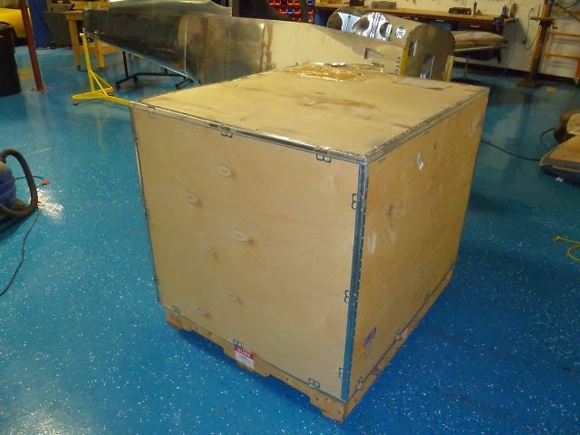
It's here, it's here!  It's finally here!  Yea!


Ok it's just a box. The most expensive box I've ever purchased, but yes, it is just a box.  Until you open it of course.


Now the particulars:  

Brand:      ECI
Model:     TITAN IOX370, horizontally opposed, fuel injected, air-cooled.
Cylinders: 4
Ignition:    Electronic, Dual independent P-Mag
Induction: Normally aspirated
HP:          205

Horsepower-wise the IOX370 is very similar to a modern air cooled automobile engine like that in a Porsche 911 for example.  A normally aspirated, air-cooled 911 made about 315 HP in 6 cylinders.  Take 4 of those and you get about 210 HP at the crank.  The main difference being that the IOX370 is designed to produce its rated power continuously for its 2000 hour lifetime.  This is certainly not recommended for the Porsche owner.


And so it sits waiting on me to finish the fuselage.