Purpose

This is a blog containing the build history of an experimental home built airplane. The RV-7A is a two place, piston powered, low wing, tractor configuration, tricycle gear, aluminum and composite aircraft. The original purpose of this blog was to document the construction of my experimental category aircraft in order to satisfy the build log requirement for the FAA. Now it's just for the amusement of friends and family as I document some of our aviation experiences. For more information on the RV series of aircraft see www.vansaircraft.com.

Thursday, August 29, 2013

Step 9.4, Forward fuselage reassembly

It was very disheartening to see all of that work going away as each piece was disassembled.  Conversely, now that the pieces are going back together, this time permanently, the mood is much lighter.  After all of the priming and deburring it's very nice to get back to assembly.

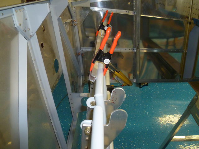
Before I assembled the forward bottom skin to the center bottom skin, I need to test fit the landing gear weldments and match drill them to the side skins.  There is an interference with the spar carry-through flange which must be ground away before the weldment will sit flat against the spar.  Pictured below is the trimmed area before final filing and polishing.  The cut gets very close to one rivet, but it is unavoidable.


After that, it was just a matter of reassembling the pieces which were all carefully marked with their part number and an arrow indicating their proper orientation, i.e., forward, up, left, or right as required.  Since there were no parts to make this time around, the reassembly via cleco went very quickly.  Please enjoy the following musical montage sans music:


When the firewall is attached to the side skins the joint is first sealed with a fire resistant silicone.  This is designed to prevent exhaust gases from entering the cockpit.  It has the added benefit that should the engine catch on fire, neither the passenger or nor the pilot will be inconvenienced by the smell of smoke.


Before the bottom skin is riveted on, the lower longerons are bolted to the engine mount weldments on the back of the firewall.


In this spectacular photo, the camera on it's own, decided the table top was the more interesting subject.


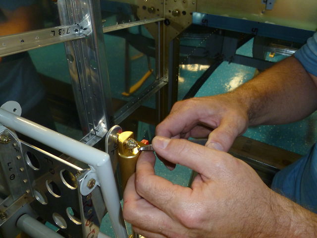
I didn't take many photos of the riveting process because Carolina and I were both involved.  For most the the process Carolina was under the plane because she prefers to buck rather than shoot.


I like that photo because she is smiling.  In the future I will show her that picture and gently suggest that this phase was not as bad as she remembers.


One of many long evenings of riveting is done.  Mercifully, it's time to go back up to the house.  


All together, it took a couple of weeks to complete this reassembly.  There are hundreds of rivets in the side and forward bottom skins and along the center to tail cone joint.  I can't say that this portion of the project was a lot of fun, just that it sure is nice to finally move on.

One of the really amazing things that the reader will not readily appreciate is the way the structure becomes very robust and unyielding as the rivets go in.  It really is a wonderful thing to watch as the flimsiest of materials quite suddenly take on a strength that would be unsuspected to all but the structural engineer.

So, at this point the lower half of the fuselage is mostly complete.  Enough of the structure is riveted together that the fuselage can now be self supporting.  This means the fuselage can be turned over in a process known to builders as "Flipping the Canoe."  Since the bottom of the fuselage is not flat, most builders construct some kind of cradle to hold the fuselage and to raise it to a comfortable work height.

Some claim time and effort savings if a giant rotisserie is constructed to allow the fuselage to rotate to any comfortable angle which will facilitate access.  My motto has always been "If there is a way to save time, I'll do it no matter how long it takes."  Here are a few shots to get the flavor of this little side project.  The rotisserie is made primarily from rectangular steel tube, 2" x 1", a little bit of .75" square tube, and some 1" angle.


In the next posting the canoe will finally be righted, the rotisserie will be demonstrated, and the death march toward riveting madness will be a distant memory.


Wednesday, August 21, 2013

Step 9.3, Forward fuselage disassembly

Well after all of the apparent progress on the fuselage framing, its time to take a few steps back, lest we finish too early.

So as we have seen in previous postings, the build order is temporary assembly, match drill mating components, disassemble, prime, and finally reassemble.


So the pieces have all been match drilled and now they come apart.  I like this view because with the side skin off, it resembles a cut-a-way drawing.


Going,


Going,


Gone!


So sad to be back here again, but its all necessary so that we can debur, dimple and prime.  Here are the forward longerons -- deburing in progress.


One row dimpled and one to go on the side skin to tail cone interface.


Most of the longerons are too thick to dimple, so they must be machine counter sunk.


Here is the main longeron in process.  I guess I should have made my shop bigger.


And at this point I discovered that I failed to match drill a couple of holes in one of the longerons.  Since I already had the skins off there was nothing to locate the hole's locations without reassembling the longeron to its mating side skin.  Fortunately, I remembered reading about this happening to another builder who used his other longeron (which had the holes) as a reference to locate the missing ones.  After clamping the two back to back the whole calamity was quickly averted.  Here is a photo with the longeron ready to be drilled.  The missing holes were in between the two sets of clecos.


Nut plates being attached to the back of the side skins to attach the steps.


And thats all he wrote.  Well, not quite. I'll finish this posting by noting that the reader has been spared the life threatening tedium of  a lot of pictures of the seemingly endless parade of deburring and dimpling that followed the teardown.

So to recap where we are:  All of the forward fuselage frame, from the tail cone to the firewall, has been disassembled, deburred, dimpled and primed.  In the next post, Carol the riveter returns as she helps me to permanently reassemble the newly prepared pile of parts.


Saturday, August 10, 2013

Step 9.2, Rudder pedals

I've been in a rush to get as much accomplished as possible before taking a week off for Oshkosh '13. Consequently, I have not been taking many pictures.  This is a significant problem for the reader as I rely heavily on the pictures to clarify my confusing text.  In this posting I'll assemble the rudder pedals and brakes.  Then test fit the assembly in the forward fuselage so that the mounting holes can be located and drilled.

First, the pieces are collected and readied for assembly.  


This airplane will have brakes for both the pilot and passenger.  Why does the passenger need brakes? They don't, but having the brakes on each side allows the plane to be flown from either side. There are eight stiffeners and four brake cylinder flanges to attach to the four brake pedals.


The four pedals complete.

The rudder pedals are a welded steel framework that is attached to the fuselage by plastic bearing blocks. The bearing blocks come pre-drilled for the steel rudder pedal framework, but they must be drilled for the mounting points.  Once the holes are drilled, the center block (black) is split lengthwise to allow either side of the block to close around the rudder pedal.


The brakes operate by pressing the toe pedal which is the silver part in the picture below.  The toe pedal rotates backward, which in turn, compresses the brake cylinder (gold).


When the rudder pedals are in place, the bearing blocks are match drilled to the longerons on either side of the fuselage.  Then the pedals are aligned straight with clamps so that the brake cylinders can be fitted and drilled to the flanges as shown in the center lower portion of the picture below.


Sadly, I did not get a picture of the complete rudder pedal assembly installed.  But, I do have this one:


Which is me trying to connect the brake cylinders and install the assembly while standing inside the forward fuselage.


The brake pivot bolts are all retained with castle nuts and cotter pins.

And finally, I mentioned that I went to Oshkosh.  There were lots of interesting homebuilts to see.


And interesting people.


But I was there on a mission.  I needed an engine.  So after shopping around for a day and a half...


I am the proud owner of an ECI Titan IOX370.  Yep, that's me wincing at the cost of it all.  A historic photo if I ever saw one -- It seems to have captured the exact moment when the sum total was revealed.  J.B., the gentleman on the right, was very helpful in answering questions and helping me to configure the motor. I should also mention that Miguel who is not pictured, was also very helpful.

The next posting will be the big tear down. Tune in next week and find out what that's all about.


Tuesday, August 6, 2013

Step 9.1, Forward fuselage framing

In the last post I completed the attachment of the steps.  Now I 'll be moving up to the front of the airplane and framing in the longerons and stiffeners on the forward fuselage.  The forward fuselage is the section between the main spar and the firewall.  Functionally, the forward fuse section is where your legs and feet go.  Structurally, it supports the weight and thrust of the engine.

First the firewall which was completed in step 8.1 is clamped to the side skins to temporarily hold it in place. Then the bottom skin is set in place.  Since the bottom skin is match drilled to the spar, the precise location of the firewall can be set relative to the bottom skin and side skins.  The firewall flange is then match drilled to lock in its position.


Next holes are cut in the bottom skin to allow the landing gear struts through.  Vans provides a template for the oval shape for which I am grateful.  I hope the fit is good.  I won't know for a while yet.


I wasn't entirely sure how to go about cutting the hole so I started with a roto-zip saw.  The aluminum was too much for the lightweight drywall bits that I had, so I moved on to a sabre saw.  The radius of the cut was too tight for the 5/16" wide metal cutting blade, but I was able to make do with that by frequently backing up and turning in to make a sharper turn.  A little filing to finish and it's all good.


Carol has been cranking out a lot of the small parts like these flanges that help tie the big pieces together.


Here is an inside look at the framing.  The horizontally oriented longerons carry the loads back from the firewall to the main spar.  In the photo below, the firewall is just out of frame to the right.  The fuselage is upside down so the gold colored structure at the upper left is the main spar carry through.


To complete the forward framing the lower longerons are fabricated and then match drilled to the lower forward weldments.  First cut the angle stock to length:


 The inside radius of the cutout is just a 1/4" hole.


The rest of the cut out is done on the band saw.


The finished longerons are filed smooth and then a twist is applied to allow the otherwise straight angle to conform to the tapering nose of the fuselage.

The next step is to match drill the longerons to the skins and to drill for AN3 bolts that go through the weldments.

Mark and drill.


Ream to final size: 3/16"


That completes the forward framing.  Please remain seated until this posting ends.