I've been in a rush to get as much accomplished as possible before taking a week off for Oshkosh '13. Consequently, I have not been taking many pictures. This is a significant problem for the reader as I rely heavily on the pictures to clarify my confusing text. In this posting I'll assemble the rudder pedals and brakes. Then test fit the assembly in the forward fuselage so that the mounting holes can be located and drilled.
First, the pieces are collected and readied for assembly.
First, the pieces are collected and readied for assembly.

This airplane will have brakes for both the pilot and passenger. Why does the passenger need brakes? They don't, but having the brakes on each side allows the plane to be flown from either side. There are eight stiffeners and four brake cylinder flanges to attach to the four brake pedals.


The four pedals complete.
The rudder pedals are a welded steel framework that is attached to the fuselage by plastic bearing blocks. The bearing blocks come pre-drilled for the steel rudder pedal framework, but they must be drilled for the mounting points. Once the holes are drilled, the center block (black) is split lengthwise to allow either side of the block to close around the rudder pedal.


The brakes operate by pressing the toe pedal which is the silver part in the picture below. The toe pedal rotates backward, which in turn, compresses the brake cylinder (gold).


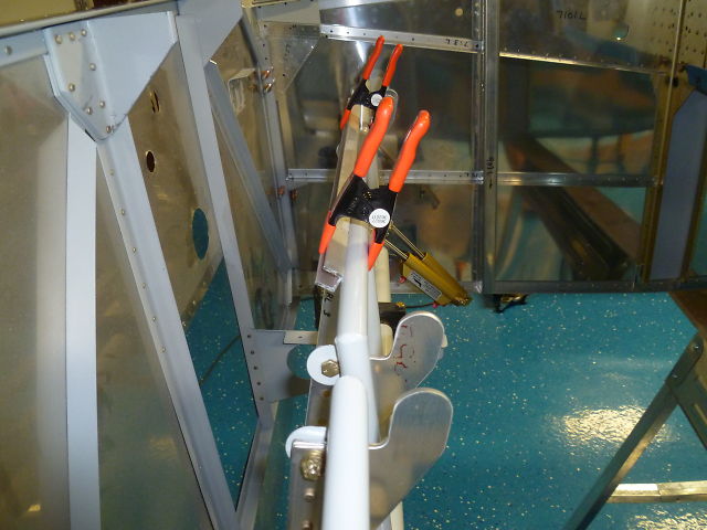
When the rudder pedals are in place, the bearing blocks are match drilled to the longerons on either side of the fuselage. Then the pedals are aligned straight with clamps so that the brake cylinders can be fitted and drilled to the flanges as shown in the center lower portion of the picture below.
Sadly, I did not get a picture of the complete rudder pedal assembly installed. But, I do have this one:

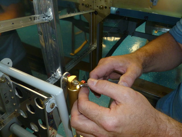
The brake pivot bolts are all retained with castle nuts and cotter pins.
And finally, I mentioned that I went to Oshkosh. There were lots of interesting homebuilts to see.

And interesting people.

But I was there on a mission. I needed an engine. So after shopping around for a day and a half...

I am the proud owner of an ECI Titan IOX370. Yep, that's me wincing at the cost of it all. A historic photo if I ever saw one -- It seems to have captured the exact moment when the sum total was revealed. J.B., the gentleman on the right, was very helpful in answering questions and helping me to configure the motor. I should also mention that Miguel who is not pictured, was also very helpful.
The next posting will be the big tear down. Tune in next week and find out what that's all about.
No comments:
Post a Comment