Purpose

This is a blog containing the build history of an experimental home built airplane. The RV-7A is a two place, piston powered, low wing, tractor configuration, tricycle gear, aluminum and composite aircraft. The original purpose of this blog was to document the construction of my experimental category aircraft in order to satisfy the build log requirement for the FAA. Now it's just for the amusement of friends and family as I document some of our aviation experiences. For more information on the RV series of aircraft see www.vansaircraft.com.

Wednesday, February 29, 2012

Step 2.2, Vertical Stabilizer done!

Well, I had planned to detail the riveting process in this post.  But, I was working by myself during this phase and I had no one but Roxy to take any pictures.  And her photos always have an avant-garde quality about them that takes certain liberties with photographic composition.

All of the rivets attaching the skin, except those around the edges, are bucked using the rivet gun and bucking bar.  One arm goes inside the VS holding the bar and the other arm holds the gun.  A third arm at this point would be useful to place the next rivet.


The process of bucking a rivet is pretty easy.  Put the rivet in the hole and smash one end with a rivet gun while other end is held immobile against a bucking bar.  The rivet gun is simply a pneumatic hammer and the bucking bar a heavy piece steel, or in my favorite example, a piece of tungsten.
For the rivets around the periphery of the VS, the pneumatic squeezer will reach and this is my preferred rivet treatment as it is probably 4 times faster than bucking.


Carolina applies the finishing three pull rivets to the middle rib that can not be reached with solid rivets once the rear spar is in place.


So the vertical stabilizer is done for now and is safely stored out of the way.  The next step will be the rudder.

Roxy and Trina discuss a technical matter.

Sunday, February 26, 2012

Step 2, Vertical Stabilizer

So without much ado, or really any ado whatsoever, I moved the horizontal stabilizer up to the storage area and on the same trip up brought the vertical stabilizer parts down.  This is just the kind of hyper efficiency that I hope will see this project complete in less than 20 years.

Vertical stabilizer ribs

Vertical stabilizer rear spar
The vertical stabilizer is going together very quickly.  In the photo at right he rear spar and spar doubler  are assembled and match drilled about a half an hour after the parts hit the work bench.  So with the completion of the HS and this work on the VS we decided that was enough excitement for one evening.  But before leaving for the night, Carolina eliminates steel and aluminum shavings from the match drilling mess.

Vacuumer extraordinaire
The process of taking a preformed part from Van's kit to a completed assembly is fairly simple:  Attach a  part using clecos to its adjoining parts, match drill, disassemble, debur all of the edges and holes, protect the aluminum with some kind of primer, reassemble, and finally, rivet.  That's it, you're one step closer to owning an airplane.  Ok, ok, I might have left out a few steps like dimpling, measuring, trimming, and a  lot of staring at plans, but that is basically it.  So in this post I'll go in to a little more detail on the various processes that Van's has thoughtfully added to prevent the ending from happening too soon after the beginning.

1. Assemble the parts:
The next day was a simple matter to assemble the skeleton and get the skin ready to be matched drilled to the VS spars and ribs.


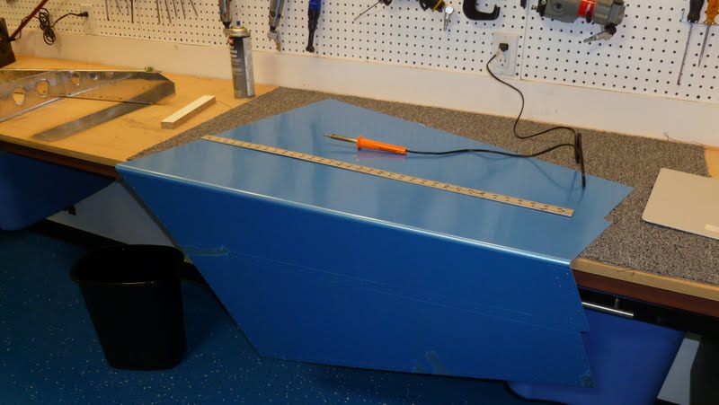
After the skeleton is assembled, the vertical stabilizer skin is prepared.  The first step is to remove the protective plastic coating in the vicinity of where the rivets will be.  The bulk of the plastic is left on to protect the skin from scratches that would otherwise find their way on to the skin during the build process.


The secret to this, well known by Van's aircraft builders, but forbidden knowledge to all others, is to use a soldering iron to lightly melt the plastic away in lines straddling the rivet line. Once the plastic is scored it can be removed neatly.


Finally, the vertical stabilizer skin is clecoed on to the skeleton.

2. Match drill:
Match drilling applies to the Vans pre-punched kits only.  In a pre-punched kit, most of the holes are located in the skins, ribs, and/or spars at the factory by a computer.  This eliminates the step of measuring and laying out the hole locations.  One still needs to determine the proper diameter to drill, but the pre-punched hole, which is smaller than the finished hole will be,  is used as a guide to locate the hole.  The result is a kit that is assembled with all of the precision and accuracy a HAL-9000 can provide.

Here Carolina demonstrates the little known sport of match drilling while a puppy attacks your foot.  It was about to become a winter Olympic game, but cooler heads prevailed and the Olympic committee selected curling instead.


3. Disassemble:
The next step is to disassemble the whole thing after carefully marking the name and orientation of any piece that could be reassembled incorrectly after priming later.

4. Debur:

The deburring process knocks off any chips and smooths the edges of the drilled holes to make them safer to handle and to reduce the possibility of stress cracks emanating from scratches or nicks.  In addition to the holes, the edges of all parts are also deburred  for the same reason.


Meanwhile...  I'm smoothing the edges of the VS-808 spar doubler.


We found that deburring tool wouldn't fit into the small ends of the spars, but the right angle drill would.


My next task was counter sinking the lower section of the spar doubler.


5. Prime:
And then all of the parts except the skin go into the paint booth for primer.  I'm not priming the skins because they are already coated on both sides with a thin layer of pure aluminum that is corrosion resistant (Alclad).


6. Dimple:
While the primer is drying, we dimple the skin to accept flush (counter sunk) rivets.  Dimpling refers to an intentional dent placed into a skin, rib or spar that is used as a counter sink just the right size to hold a rivet such that the rivet face sits flush with the surface of the skin.


An ancient pearl of aircraft wisdom: When the skin is dimpled, so too must the underlying structure be dimpled to accept the dimple above it. While the author of this gem has been lost to history, it illustrates the ripple effect in added work caused by wanting a cleaner looking and possibly faster airplane. Not to mention all of the added tooling required. Although Cessna would disagree (famous for not using flush rivets), I think it will be worth the extra effort.


And so ends this post with the dimpling of the skin, spars, and ribs.  Next, post I be attacking the final step: reassembly and riveting.


Thursday, February 23, 2012

Step 1.2, HS Done!

Top skin 100% + 9 rivets
The nose and end cap ribs are placed in between the skins and forward spar.  Since they were previously dimpled, they just snap right into position and after a few clecos to make sure they don't move, they are attached using the squeezer.  In this photo one of my mistakes can be seen.  Wait for it... See the rivets next to the little arrows.  Yes?  Well you shouldn't.  I was having so much fun with the squeezer, I accidentally put rivets in those holes that were supposed to be left open.  By a merciful act of divine providence, I caught the error before I had filled each of the ten open locations.  It was my good fortune that I only had to drill out nine.


After the ribs are in place the rear spar assembly is set in place.  Since all of this was previously match drilled, the fit is very near perfect.

Rear spar in place

The HS is propped up to make squeezing the rear spar rivets easier

The last step is to use pull-rivets to fix the ends of the two middle ribs to the rear spar.  Shown below is the Harbor-Freight pneumatic/hydraulic rivet puller.  This is an awesome tool and inexpensive too!


LP4-3 pull rivets in place

HS complete!

And now, on to the vertical stabilizer...


Tuesday, February 21, 2012

New helper joins Rough and Ready Aerospace

We found a companion for Roxy and at the same time, a very efficient means for injecting chaos directly into our household. An 8 week old Border Collie and Australian Sheppard mix named Trina.  We think she looks more like a Brittany Spaniel.  Why is this in an airplane build log?  I don't know.  I just like showing her off.  She's gifted, you know.


Dogs and Airplanes :)
Trina with her new mommy

Trina ready for her close up.  12 weeks.

The shop dog?

Ever helpful, Trina prevents me from floating away.

Step 1.1, HS continues

In the previous episode we saw the protagonist flying his assembled, but not yet riveted horizontal stabilizer about the shop.  The interested reader will be relieved to see that the stabilizer has made a safe landing back on the work bench and is ready for the skins to be attached.  I thought it prudent to begin on the bottom side while our riveting skills improve.


And so we bucked our first rivets.  We found it challenging to get a tight fit between the skin and spar at first, but a little experience plus a setting tool I made really got things going.
Setting tool
The setting tool is just a piece of steel with a female dimple die counter sunk into the end, and then a shallow hole drilled into the bottom of that to accept the shaft of the size rivet in question.  In this case an AN426D3-3.5.  I have observed these tools before in pictures from Vansairforce forums and in some other blogs, but I didn't know what they were for until I faced this problem.  I just love the "Ah Ha!" moment when a problem is solved -- or in this case, the purpose of a mystery tool is discovered.

Most of these setting tools that I have seen pictured have been drilled right into a bucking bar, but I couldn't quite see myself taking a drill to my brand new tools, so I just used some scrap 1" x 1/4" mild steel I had laying around.  Because of its light weight, the tool is a little uncomfortable when the 3x rivet gun is hammering from the other side.  Fortunately not every rivet needs it!

And so the bottom skin and then the top skin are attached to the forward spar and the middle ribs.  I found that the top skin did not need the setting tool as much because the skin was pulled down tight to the spar instead of open as in the picture above.  In retrospect, I don't think it saved any time to do the bottom skin with top open.

Done riveting for the night.  Carolina and Roxy preparing to bug out.

Flush rivets along top skin

 The six ribs on the ends and the aft spar are next.  These can be reached with the squeezer.

Finally, I thought I would mention my parts caddy which has turned out to be a real time saver.  A Harbor-Freight mobile parts rack with a white board attached to the top.  The plans are held on by two clip board clamps bolted to the top.  Fold the plans over the top and the white board is usable.  In the parts bins it's mostly rivets and clecos.  But the true utility is that the parts are so easily accessible and nicely labeled by Carolina.

Roll around parts caddy with plan holder attached


Friday, February 10, 2012

Step 1, Horizontal Stabilizer

So I officially became an aircraft builder on January 1, 2012.  Here is the obligatory first rivet photo.  Great! One down and 20,000 to go!  To build a Vans aircraft in the normal build order, one starts at the rear and works towards the propeller.  The RV 7A airplane consists of 4 major kits, empenage (tail), wings, fuselage, and finishing kit.  None of the four kits contain the engine or avionics so they must be purchased separately.


The keen observer will note the the date written below the first rivet is a week later than my official start date.  This is because the first rivet comes after several steps are completed on the rear spar of the horizontal stabilizer.  The component pictured is a bracket holding the elevator hinge bearing to the rear horizontal stabilizer spar.

Before one can begin driving rivets, one must first obtain the empenage kit from Vans.  Here is what I saw sitting on my porch after returning home from work one day.


It is a surprisingly small package considering the size of the completed tail.  We thought the writing on the box "High dollar Aircraft Parts" was kind of funny.  But not at all inaccurate. 


The contents were well packed. My wife, Carolina, was nice enough to do the inventory for me.  Then after my shop was very nearly complete we started work on the empenage: 
Plan set and build manual
Match drilling spar reinforing bars to rear HS spar
Rear HS Spar
Carolina, deburing machine
Forward HS spar
Carolina squeezes first rivet
Rear HS spar components during priming

Carolina on the lookout for aluminum shavings
Forward HS spar assembly


Match drilling HS skeleton with skins

Top side drilled. flip HS and repeat

Assembled HS takes flight