 |
| Vertical stabilizer ribs |
 |
| Vertical stabilizer rear spar |
 |
| Vacuumer extraordinaire |
The process of taking a preformed part from Van's kit to a completed assembly is fairly simple: Attach a part using clecos to its adjoining parts, match drill, disassemble, debur all of the edges and holes, protect the aluminum with some kind of primer, reassemble, and finally, rivet. That's it, you're one step closer to owning an airplane. Ok, ok, I might have left out a few steps like dimpling, measuring, trimming, and a lot of staring at plans, but that is basically it. So in this post I'll go in to a little more detail on the various processes that Van's has thoughtfully added to prevent the ending from happening too soon after the beginning.
The next day was a simple matter to assemble the skeleton and get the skin ready to be matched drilled to the VS spars and ribs.


After the skeleton is assembled, the vertical stabilizer skin is prepared. The first step is to remove the protective plastic coating in the vicinity of where the rivets will be. The bulk of the plastic is left on to protect the skin from scratches that would otherwise find their way on to the skin during the build process.
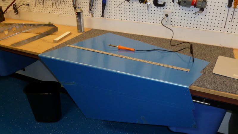
The secret to this, well known by Van's aircraft builders, but forbidden knowledge to all others, is to use a soldering iron to lightly melt the plastic away in lines straddling the rivet line. Once the plastic is scored it can be removed neatly.


Finally, the vertical stabilizer skin is clecoed on to the skeleton.
2. Match drill:
Match drilling applies to the Vans pre-punched kits only. In a pre-punched kit, most of the holes are located in the skins, ribs, and/or spars at the factory by a computer. This eliminates the step of measuring and laying out the hole locations. One still needs to determine the proper diameter to drill, but the pre-punched hole, which is smaller than the finished hole will be, is used as a guide to locate the hole. The result is a kit that is assembled with all of the precision and accuracy a HAL-9000 can provide.
Here Carolina demonstrates the little known sport of match drilling while a puppy attacks your foot. It was about to become a winter Olympic game, but cooler heads prevailed and the Olympic committee selected curling instead.


3. Disassemble:
The next step is to disassemble the whole thing after carefully marking the name and orientation of any piece that could be reassembled incorrectly after priming later.
4. Debur:

Meanwhile... I'm smoothing the edges of the VS-808 spar doubler.


My next task was counter sinking the lower section of the spar doubler.

5. Prime:
And then all of the parts except the skin go into the paint booth for primer. I'm not priming the skins because they are already coated on both sides with a thin layer of pure aluminum that is corrosion resistant (Alclad).

6. Dimple:
While the primer is drying, we dimple the skin to accept flush (counter sunk) rivets. Dimpling refers to an intentional dent placed into a skin, rib or spar that is used as a counter sink just the right size to hold a rivet such that the rivet face sits flush with the surface of the skin.

An ancient pearl of aircraft wisdom: When the skin is dimpled, so too must the underlying structure be dimpled to accept the dimple above it. While the author of this gem has been lost to history, it illustrates the ripple effect in added work caused by wanting a cleaner looking and possibly faster airplane. Not to mention all of the added tooling required. Although Cessna would disagree (famous for not using flush rivets), I think it will be worth the extra effort.

And so ends this post with the dimpling of the skin, spars, and ribs. Next, post I be attacking the final step: reassembly and riveting.
No comments:
Post a Comment