Purpose

This is a blog containing the build history of an experimental home built airplane. The RV-7A is a two place, piston powered, low wing, tractor configuration, tricycle gear, aluminum and composite aircraft. The original purpose of this blog was to document the construction of my experimental category aircraft in order to satisfy the build log requirement for the FAA. Now it's just for the amusement of friends and family as I document some of our aviation experiences. For more information on the RV series of aircraft see www.vansaircraft.com.

Friday, March 30, 2012

Step 4.2, Right Elevator Frame

After all of the elevator innards are primed, the right elevator skeleton is assembled.


Start with a bunch of flimsy parts.


And after a bit their combination begins to make something substantial.  This is a nut plate that will attach one the elevator rod end bearings.  Note the reinforcing plate surrounding the nut plate.  This spreads the force applied to the nut plate over a larger area of the spar.  There are actually very few parts on the aircraft that are made from iron.  The nut plate is one common part that is, as an aluminum nut plate if they even exist, would not have the requisite strength.


Here's another part that is made of steel.  The elevator horn, #605-R.  This part transmits the force applied in the cockpit to the elevator surface.  The ninety degree turn in the alignment of the flanges changes the back and forth movement of the control stick to an up and down motion on the elevator.


Finally the right elevator skin, having been match drilled and dimpled, is ready to rivet to the skeleton.


Not shown at this point, is a step where RTV rubber is squirted into a blob and the ends of each stiffener along the trailing edge just prior to closing the skin.  This step is said to prevent cracking of rivet holes along that line.  It may be controversial, but I'll stick my neck out right here and state flatly, that I am 100% against cracking of any part on my plane.


Using the squeezer to close up the right elevator skin.


Finally move the right elevator out of the way to begin the left.


Right elevator done!

Monday, March 26, 2012

Step 4.1.1, Elevator counter weight revisited

I think I mentioned in the previous post that I had some difficulty with drilling the holes in the center of the forward flange of the tip rib and counter weight rib.  It was during the reassembly of those parts after priming that I finally pieced together what had gone wrong.  It seems that when Chuck and I assembled the counter weight skins prior to drilling the counter weights, we both got it backward or more accurately, upside down.  It was pretty obvious when viewed in conjunction with the elevator skin but somehow it was not at all obvious to us at the time not having the elevator skin as a reference.  So in this case, two heads were just as bad as one!  The only harmful effect is that the holes in the forward flange of the tip and counterbalance ribs are not centered, but are still usable.   However, the holes in the counter balance weights are in the wrong place once the counter balance skin is flipped the other way.


To correct this flub, I first plugged the holes along the back side with some aluminum tape.


Then a piece of lead that was previously cut off, is melted and allowed to drip into the holes completely filling both holes.


Finally the excess is filed off and the holes are re drilled and countersunk.  An hour later I was back in business and making progress on attaching the elevator skin.  Which will be the subject of the next post.


Friday, March 23, 2012

Step 4.1, Elevator frame

The rudder frame is constructed in very nearly the same fashion as the rudder.  A main spar with ribs on the ends and stiffeners in the middle.  With the elevators, the skin is folded along the trailing edge which alleviates the need to do the double flush riveting that provided so much entertainment on the rudder.  However, the skin is not bent to the finished angle so that clearance is provided to rivet the stiffeners.  The next step after the stiffeners are attached is to bend the skins down to their finished angle.  Vans provides figure 5-7 in the build manual depicting a brake made of 2x8s.  The accompanying text is along the lines of 'build one of these to bend your skins.'  There are no dimensions or suggestion of how much to bend.  Helpfully, the build manual does provide a picture illustrating good bends and bad bends.  At the very least, I'll be able to recognize my elevator as one of the bad ones :(


I briefly considered calling the factory for guidance, but I suspect that their answer would  most likely be:  'Be careful to bend it just the right amount.'   

Besides, I don't want my file at Vans to be marked "This guy is helpless", or worse, so I think it better to just follow Vans most famous and time honored advice: It's not a rocket ship, build on!


This looks worse than it is.  It springs back.

So the squeezing wasn't quite as hard as I thought.  It looks like I got one of the good ones.  Now that the skins are squeezed, it's time to move on to the elevator frames.  This is a matter of fitting the  backing plates behind the spar in the area of the hinges (rod end bearings) and fitting the counter balance, counter balance skin and tip ribs.


Chuck came by to help out on this evening's work so we each took an elevator.  One area of difficulty was in  drilling the lead counter balances themselves.  It turns out that lead is some sticky stuff and it made the drilling much more difficult than I would have imagined.  And, I managed to get the holes off center on the counter balance rib's forward flange, but I think I will be able to properly deal with it later during final assembly.


I didn't take any pictures of the counter balance preparations, but the lead weights are first trimmed, then match drilled with the counter balance skin, and finally, counter sunk for the two retaining bolts. 


Finally, the tip assembly is partially disassembled to remove the counter balance weights and then reassembled with the spar in preparation for match drilling the skins.


The next evening, I finish the right elevator frame assembly and match drill the spar, tip ribs, elevator horn, and of course the skin.  After all that the elevator is disassembled for deburring.  


Carolina comes down to help out with the deburing and pre-priming preparations. Which is basically a light once over with a Scotch-Brite pad.


You've waited long enough.  So here it is, tonight's vacuuming action...


Wednesday, March 21, 2012

Step 4, Elevator

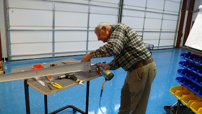
The right and left elevators are constructed more or less in parallel.  The first step, like the rudder before it, is to trim some angle material to length for stiffeners.  Fortunately for me, Chuck has stopped by again to help. First up, remove the blue plastic from the inside of the left and right skins.


  Chuck trims the angle at the band saw while I mark them for location and size.


Next the stiffeners are smoothed on the Scotch-Brite wheel and then clecoed to the skins for match drilling.


After match drilling, the holes are dimpled to accept the dimples in the skin and the skins are dimpled to accept the flush rivets.  


And the then roughed up with a Scotch-Brite pad to prepare for priming.

stiffeners from right elevator

The blue plastic is removed in strips along the rivet lines on the outside.


So now the skins need to be dimpled but there is not enough room between the last hole in the stiffener rivet line and the fold in the skin to use the DRDT-2 dimpler.  My vise grip dimpler, and my pneumatic squeezer aren't getting it either.  Fortunately, I remembered the pop-rivet dimple dies that came with the Isham tool kit.  It's funny,  I remember thinking that I probably wouldn't be using those when I first saw them during the tool kit inventory.  Lucky for me, I hadn't deleted them from the tool kit when I made the order.  At that time I didn't even know what they were for...


The last hole next to the bend needs to be dimpled.  Here is the pop-rivet die set for an AN426AD3 rivet. 


Outside of skin

Inside of skin

With the stiffeners primed I was ready to back rivet them to the right elevator skin.


And Carolina goes to work placing rivets in the left skin.


Oops.  Left skin stiffeners are not dimpled.  Carol springs into action on the DRDT-2.  


And then continues on by riveting the trim servo inspection cover baking plate.  Her main concern at this point is obviously frostbite.  Understandable, as the inside temperature had dipped somewhere south of 65 deg F.


As the stiffeners are finished I'm beginning to think about ordering the wing kit.  With an eight week lead time, I think I should have ordered it 6 weeks ago.

Monday, March 19, 2012

Step 3.5, Rudder finished!

Here are some more pictures to finish off the rudder build.  These first pictures are out of order as they were taken during the rudder frame assembly, but I didn't feel like I had enough to make an worthwhile blog post. So I'll throw them in here to complete the rudder section of this blog.

While riveting a backing plate to the spar I created this common imperfection known to aircraft builders as a 'smiley.'  Although in this orientation it's more of a 'frownie', like my face when I first spotted it.


These are definite no-nos, so the little booger must come out.  First thing is to drill through the head just down to the level of the shank.  One must be careful at this point to not drill through as this would most likely enlarge the hole in the parts being mated.


With the head drilled, a pin punch the same size as the drill is placed into the hole and gently rocked back and forth until the head breaks off.  Then the punch is used to hammer the shank through the hole.  If you've done it correctly, a new rivet can be placed into the same hole and you get another whack at it.


My friend Chuck came over to help me while I was putting the rudder frame together.
Last rivets in the rudder frame.
Then it's time to rivet the skins to the frame.  Not a lot of pictures here.  But, this one shows the intersection the left rudder skin and the counter balance skin.  The numbers are the rivet sizes which vary depending on whether the rivet is going though just the skins, or through the skins and spar or top rib.


At this point, I think I'm about ready to rivet the trailing edge.  And then I see two parts sitting on my work bench.  Oh #@$%^!,  I've left out the R918s.  These were the pieces that Carolina had prepared in a previous post.  I would be in the doghouse if I left these off.  Also, I wouldn't be able to attach my lower rudder tip.  Which would, no doubt, be an unwanted conversation item while standing around at the fuel pump.  


The final step to complete the rudder is rolling the leading edge.  Pictured below is the J-bolt method in practice.  The picture is too close to understand what is going on here, but rest assured that everything is in order.  The left and right skins extend beyond the spar and are rolled into a semicircle to meet in the center.

To roll the skins they are first attached to a length of 3/4" iron pipe, although a pipe made of just about any material except foam rubber would probably work just fine.  What is seen in the picture is the duct tape attaching skin to pipe with the skin not quite visible under the pipe.  The J bolts are in this case a U bolts with one leg cut off (or 11 letters).  When the pipe is turned the skin is pulled along and formed into a pleasing aerodynamic shape.


Well, that is the theory.  In practice it also took a considerable amount hand forming, bending, squeezing, pressure, and some profanity to accomplish.


Finally the completed rudder.  All that is left at this point is to install the rod end bearings.  To make that job easier, I constructed an installation tool as detailed on Sam Bucanan's web site.  Thanks Sam.


Next post:  The elevator begins.