At last I'm finally going to work on the canopy. I've been alternately looking forward and dreading this task. On the one hand it will be a major milestone toward the completion of this project. But on the other, it is rumored to be one of the most difficult aspects of the plane's construction. The difficulty here is that the canopy assembly, when finished, must fit precisely along its entire perimeter. This should be no problem at all if we can assume just four things: 1, the longerons were bent symmetrically -- perfectly following the plan's curve. 2, that the roll bar was built to the correct width and height and slopes back at just the right angle. 3, that Van's has supplied a forward canopy frame assembly that just happens to match the existing fuselage dimensions. And finally, 4, that the holes for the hinge pins can be precisely located in a difficult to reach area. The trouble is that none of these assumptions are very likely at all.
Before I start, I will address the airplane in an unmistakably serious tone making it very clear to the airplane that this step is going to be completed, no matter what. All resistance is futile, and that I am very well prepared to use all manner of hammers, pliers, and clampy things that Harbor Freight can supply.
First up: a test fit of the welded aluminum canopy frame supplied by Van's. Ok, so far, it fits the skin on the bench in the front but not along the back. Other builders have reported the same thing.

The next step is to place it on the plane and position it for drilling the hinge pins. Once on the aircraft, it is apparent that the frame's bow and the width of the frame at the rear of the weldment are not correct. Bow, in this sense, is the canopy's top curvature that must match the forward bulkhead. The bow problem is addressed by brute force and some fluting. The width of the weldment is easily changed to match the width of the fuselage at this point since the top skin has not yet been drilled.


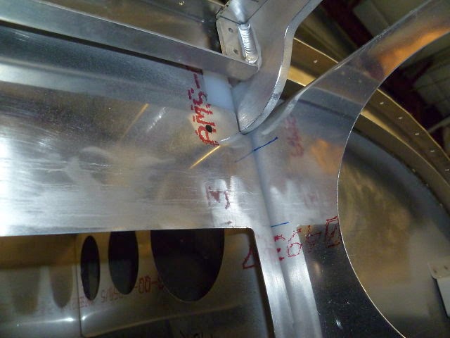
This is a view of the hinge (top center). The holes for the hinge pins will be drilled through these when they are properly located.
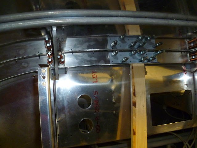
First the forward portion of the canopy frame is clamped down into position.

The splice plate and hinge supporting structure are clecoed down tight. Then a drill is run through the fuselages hinge pin holes and on into the hinge. This makes a mark where the hinge pin hole should be drilled.

The hole size is progressively enlarged on the drill press until its just under 3/8". The final step is the reamer bringing the hole size up to exactly .375".

Once reamed to size the bronze bushing is pressed in using the pneumatic squeezer.

Presto! one down one to go.

So now its time to rivet the rest of the frame together.

Here it the torture device I've constructed to force the aft hoop of the canopy frame into the correct dimensions.

Riveting the top skin.

The under side of the forward canopy frame gets some re-enforcement.


And so eventually it all goes together.
