Purpose

This is a blog containing the build history of an experimental home built airplane. The RV-7A is a two place, piston powered, low wing, tractor configuration, tricycle gear, aluminum and composite aircraft. The original purpose of this blog was to document the construction of my experimental category aircraft in order to satisfy the build log requirement for the FAA. Now it's just for the amusement of friends and family as I document some of our aviation experiences. For more information on the RV series of aircraft see www.vansaircraft.com.

Sunday, May 18, 2014

Step 11.7, Canopy frame

At last I'm finally going to work on the canopy.  I've been alternately looking forward and dreading this task. On the one hand it will be a major milestone toward the completion of this project.  But on the other, it is rumored to be one of the most difficult aspects of the plane's construction.  The difficulty here is that the canopy assembly, when finished, must fit precisely along its entire perimeter.  This should be no problem at all if  we can assume just four things:  1, the longerons were bent symmetrically -- perfectly following the plan's curve.  2, that the roll bar was built to the correct width and height and slopes back at just the right angle.  3, that Van's has supplied a forward canopy frame assembly that just happens to match the existing fuselage dimensions.  And finally, 4, that the holes for the hinge pins can be precisely located in a difficult to reach area.   The trouble is that none of these assumptions are very likely at all. 

Before I start, I will address the airplane in an unmistakably serious tone making it very clear to the airplane that this step is going to be completed, no matter what.  All resistance is futile, and that I am very well prepared to use all manner of hammers, pliers, and clampy things that Harbor Freight can supply.

First up: a test fit of the welded aluminum canopy frame supplied by Van's.  Ok, so far, it fits the skin on the bench in the front but not along the back.  Other builders have reported the same thing.


The next step is to place it on the plane and position it for drilling the hinge pins.  Once on the aircraft, it is apparent that the frame's bow and the width of the frame at the rear of the weldment are not correct.  Bow, in this sense, is the canopy's top curvature that must match the forward bulkhead. The bow problem is addressed by brute force and some fluting.  The width of the weldment is easily changed to match the width of the fuselage at this point since the top skin has not yet been drilled.


This is a view of the hinge (top center).  The holes for the hinge pins will be drilled through these when they are properly located.
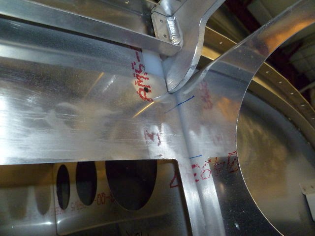

First the forward portion of the canopy frame is clamped down into position.


The splice plate and hinge supporting structure are clecoed down tight. Then a drill is run through the fuselages hinge pin holes and on into the hinge.  This makes a mark where the hinge pin hole should be drilled.
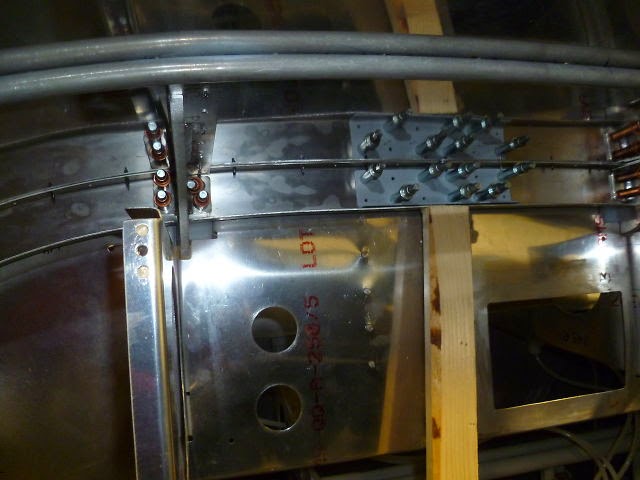

And so I did.  After taking the canopy frame back off of the fuselage, the mark can be seen.


The hole size is progressively enlarged on the drill press until its just under 3/8".  The final step is the reamer bringing the hole size up to exactly .375".


Once reamed to size the bronze bushing is pressed in using the pneumatic squeezer.


Presto! one down one to go.


So now its time to rivet the rest of the frame together.


Here it the torture device I've constructed to force the aft hoop of the canopy frame into the correct dimensions.


Riveting the top skin.


The under side of the forward canopy frame gets some re-enforcement.


And so eventually it all goes together. 


Saturday, April 26, 2014

Step 11.6, ELT

At this phase of the project my attention is being divided between a number of different tasks which has the unfortunate effect of making the progress seems slower than it actually is.  Many of these tasks are fairly trivial and don't seem to warrant a separate blog post.  Nevertheless, if I don't post regularly, my reader assumes the worst.  I assure you, dear reader, that the project is in fact progressing nicely.  

That being said, I did incur a 5 day delay to my project when I recently traveled to Southern California hunting the elusive Gorn.  Those acquainted with Star Trek will understand what a problem the Gorn can be, and may well recognize the landscape where this epic duel took place.


Alas, I didn't spot any Gorn but it was fun to look.  By the way, the location should look familiar as it has been used in literally hundreds of movies and TV shows.  Vasquez Rocks is just east of Santa Clarita CA.


This posting concerns the ELT (Emergency Locator Transmitter).  There are currently two types of ELTs used in civilian aircraft.  They are specified by the frequency on which they transmit.  121.5MHz and 406MHz.  121.5 is the old frequency that is now being phased out.  The newer frequency is the 406MHz model.  My ELT has the capability to transmit on both, but at some point in the future no one will be listening to the 121.5MHz frequency.

The 406MHz ELT signal in addition to being a beacon that can be radio located, also carries GPS information which is relayed via satellite to the would be rescuers giving them an exact location.

The ELT must be mounted within the aircraft in a specific orientation so that the radio is automatically activated in the event of a crash.  There are several suitable locations, each having its own unique challenges. In the end, I selected a location in the tailcone.  In the photo below, the ELT is the orange box.  Below that is the mounting plate that it comes with.  To the right are the pieces of scrap aluminum that I collected to build a strong attachment to the aircraft.


So the basic idea is to mount the supplied plate to the J-stringers inside the tail cone just behind the rear baggage compartment bulkhead.  A couple to circles are cut out to lighten the mounting a bit.  On the forward and aft edges I've riveted on some light weight stiffeners. 


And here is the ELT in place.  This location is considered fairly survivable due to the proximity of major structural components.  Principally, the J-stringers and aft baggage bulkhead.  


The ELT's whip antenna is located under the rear canopy, just behind the roll bar.  Its not the best location for the antenna being so close to the roll bar, but it is fairly close to the ELT itself and the antenna should have a fairly unobstructed view of the sky through the canopy.  One problem to solve with this location was how to keep the metal antenna from touching the metal roll bar.  In addition, the whip antenna needs to bend over a bit to keep it from contacting the canopy.  My solution is a nylon standoff with a slot cut into the side to restrain the antenna.  The standoffs are held in place with nylon 8-32 screws driven in to the back side of the roll bar and retained using a self-clinching 8-32 nut.


Here's the top half of the ELT antenna.  Bonus:  In the background the interior side panel is being test fit.

Next time I move on to the canopy frame.

Tuesday, April 15, 2014

Step 11.5, Canopy latch


This week's task is to construct the canopy latch.  I'm using an aftermarket latch from JD Air that replaces the Van's latch handle with a flush mounted one.  How much this modification will increase my top speed is debatable, but I'm quite certain that it will be more effective than painting flames on the cowl or using a slanted font on my N number. I didn't think to take any photos of the latch mechanism itself, but here is Carol at work on the latch mounts which are the first step.


It seems that our dress code needs revising.

While Carol works on the mounts I am cutting a big slot into the fuselage side.  Here is the slot after the rough cut.  At this point I'm wondering if I can save the airplane.  I know that it will look better after I file it smooth.


The mounting angles and latch are riveted in place.


Then I discover that the handle can push inward slightly which is undesirable, and I think, preventable.  I cut a stop out of .032" aluminum sheet and riveted it in place at the end of the handle.  Compare to the photo above without the stop.  The tang is bent to stop the handle when it is flush with fuselage skin.


Next, the linkage is assembled.  Here is the overly complex mechanism.  The idea is that the canopy handle pushes back on the bell crank like arrangement that because of mechanical leverage increases the force applied to the canopy hold downs (top of picture). 


Here is the inside all together.


And now a view of the handle from the outside.  The button on the left presses in to release the handle which pops outward.  As the handle rotates outward the connecting rod moves rearward to release the canopy.


 This photo didn't expose properly.  Good thing I'm not paying for developing or flash cubes.  


So now I guess I should begin work on the canopy.


Monday, March 17, 2014

Step 11.4, Forward deck access

Now that the canopy release is finished I can prepare the skin that goes over the top of the front deck.  The front deck, as you may recall, is the area behind the instrument panel up to the firewall.  Most of the avionics will be located in this area.  The only access to this area is from underneath the instrument panel in the foot wells.  It turns out that this is a particularly uncomfortable place to have to work since one must lie on his back arched backward over the main spar.  I've elected to skip this entirely, as fun as it sounds, and install some access panels through the top of the forward skin.  This will come in handy when it is time to rivet the skin on as well as providing future access to the avionics, sans chiropractor.

This is the area that will be covered. Pictured is the forward deck area looking aft:


The first thing is to lay out the holes to be cut in the skin.  When an access port is added through the skin, a backing piece, called a doubler is added that strengthens the area around the hole.  The idea is that stresses in the skin are safely routed around the hole the area of the skin that is doubly thick.  In addition to strengthening the skin, the doubler also provides a flange for the access port cover to rest against.  Pictured below are the doublers and the skin ready to be cut.


Here are the doublers after the saber saw attack.


Then the doublers are match drilled to the skin.


The final step for the skin is to rivet the doublers on and also add some nut plates to secure the covers.  I also sealed the edges of the doubler to discourage water entry at this location.


With the access ports complete all that is left to finish are the covers.  Ordinarily, aluminum would be used here, but in this case I want to mount some GPS antennas underneath.  Instead, I laid up fiber glass which has the fortuitous property of being relatively transparent to radio frequencies. It allows the GPS signals right through.  So I used three layers of 9 oz. cloth to build a thickness that is close to the .032" aluminum skin. Although the fuselage is fairly flat in this area, but I laid up the access panels on top of the skin anyway to get the very slight curve built in.  


Here are the covers trimmed and counter sunk for screws.  At this point they're ready for paint prep.


And that wraps up Access Panels 101.

Wednesday, March 5, 2014

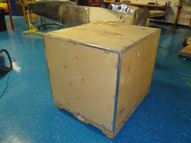
Step 11.3, Receive engine

It's here, it's here!  It's finally here!  Yea!


Ok it's just a box. The most expensive box I've ever purchased, but yes, it is just a box.  Until you open it of course.


Now the particulars:  

Brand:      ECI
Model:     TITAN IOX370, horizontally opposed, fuel injected, air-cooled.
Cylinders: 4
Ignition:    Electronic, Dual independent P-Mag
Induction: Normally aspirated
HP:          205

Horsepower-wise the IOX370 is very similar to a modern air cooled automobile engine like that in a Porsche 911 for example.  A normally aspirated, air-cooled 911 made about 315 HP in 6 cylinders.  Take 4 of those and you get about 210 HP at the crank.  The main difference being that the IOX370 is designed to produce its rated power continuously for its 2000 hour lifetime.  This is certainly not recommended for the Porsche owner.


And so it sits waiting on me to finish the fuselage.


Monday, February 24, 2014

Step 11.2, Empennage fairing

This week's task is to finish the empennage fairing.  I've been wanting to take the empennage (vertical and horizontal stabilizers) apart now that they have been fit, so that I could ready them for painting.  One last detail before I can remove them is to fit the empennage fairing.  The fairing is a molded fiberglass part that comes with the finish kit.  It is designed to cover the intersection of the vertical stabilizer, horizontal stabilizer, and fuselage.   As it comes from Van's, the fiberglass is a bit too rough for painting and the fit is, well, less than perfect.  A heat gun is used to make minor adjustments here and there, but some new fiberglass and much sanding is required to fine tune the fit.

In addition to generally improving the fit, I also want to add a lower fairing to it so that the fairing covers the gap above the horizontal stabilizer as well as below it.


So here is the basic fairing as it comes from Van's after trimming the excess.  It's not visible in the picture below, but the fairing does not extend underneath the horizontal stabilizer.  The Van's way to fill this lower gap is to fit a piece of aluminum trim to the fuselage that extends upward to the bottom of the horizontal stabilizer. I've decided to follow the lead of a number of other builders who think it nicer to add a fiber glass fairing to the bottom of the Van's supplied piece.  More on that later...


The elevator torque tubes come from the center of the fuselage area and extend through the fairing.  Carol worked on finding the limits of the tube's movement relative to the fairing. A template was made and the curve transferred to the fairing.  The fiberglass was cut back to the blue line that leaves clearance for the elevator control.


A few other notches and trims later, the fairing was fitting nicely.


The next step is to build the lower fairing.  The aluminum skin is protected with a layer of packing tape.  Then modeling clay is globbed on to pack the lower gap.  I cut a piece of aluminum with the radius that I wanted on the fairing and proceeded to scrape off all of the clay that didn't fit the radius profile.  I slapped on some automobile past wax as a release agent and I was ready to mix epoxy.  Well almost,  I cut out the strips of fiberglass first.


Next came the fiberglass and epoxy.  Four layers of 9oz. BID glass with West Systems epoxy.


It's a couple of days later and much to my surprise, the fairing comes off easily.  There may be a little more epoxy in the layup than is necessary.  The new glass is 10 to 20 thousandths thicker than the Van's supplied piece.  I didn't know ahead of time how many layers Van's used, so I consider myself pretty lucky to get even that close.  Here is the new glass (foreground) grafted on to the Van's piece after the rough trimming.


For filler I used a mixer of epoxy and micro-spheres.  The micro spheres are just little glass bubbles that take up space.  When combined with epoxy they make a very lightweight filler material that is fairly sandable.


These leading edges don't look too good, so I'm forced to go for another round of epoxy.  To get a better fit on the mating surfaces of the vertical and horizontal stabilizer, I'm going to lay up a thin layer of glass on the HS and VS directly over the leading edge part where the fit is poor.  Then, after that is almost set I will re-install the fairing with some wet epoxy on the inside to bond with the thin layer.


Now the fit is pretty good around the entire perimeter.

At this point its just a matter of smoothing everything down, filling pin holes and other minor imperfections in the surface, and match drilling the mounting holes through the fairing to the aircraft structure.

After a coat of primer it's ready for paint.


The empennage fairing has taken much longer than I expected.  Oh, well.  It's the journey not the destination  that's important -- I just have to keep reminding myself.