Purpose

This is a blog containing the build history of an experimental home built airplane. The RV-7A is a two place, piston powered, low wing, tractor configuration, tricycle gear, aluminum and composite aircraft. The original purpose of this blog was to document the construction of my experimental category aircraft in order to satisfy the build log requirement for the FAA. Now it's just for the amusement of friends and family as I document some of our aviation experiences. For more information on the RV series of aircraft see www.vansaircraft.com.

Friday, November 1, 2013

Step 10.1, Center tunnel cover

The center tunnel cover is used to hide fuel and electrical lines that are routed forward between the main spar and the firewall.  At the forward most end, the cover bends upward and forms a baffle for the cabin heat.

The cabin heat flows through the cabin heat butterfly valve on the firewall and into the cabin through louvers on the center tunnel cover.  The louvers are pre-cut by Van's (thankfully) but they must be bent outward to allow the air to pass through.


I used some of the high temperature silicone to seal along the inside seam where the heat baffle separates the hot side from the center tunnel cover.  I realize that this is mostly pointless exercise as the whole back side is not sealed against the firewall.  I have read that in the standard installation, the cabin heat is iffy at best.  And with my 4 pipe setup on the exhaust, I only get one heat muff instead of the usual two.  By my calculation, that leaves me with iffy/2. So I would like to do everything possible to encourage any heated air that might be present to flow outwards toward the pilot and passenger and not back along the firewall or down through the center tunnel.


For the most part, the cover is supplied by Van's almost complete.


So it's mainly just a matter of cleaning up the edges and setting the nut plates.  Then it is on to the auxiliary fuel pump cover.  The aux fuel pump sits above and at the aft most end of the center tunnel.  There are a few rivets to connect the sides to the top, but this is also a pretty rapid project.


Once all of the parts are assembled it looks a bit like a center console of an automobile.


One thing I've noticed about my dogs is that they can't seem to stay interested in aircraft construction.


Saturday, October 19, 2013

Step 10.0 Seat backs

The seat backs are connected to the seat pans using piano hinges.  There are three rows of hinge material on the pan to effect an adjustment in the seat back position.


Here's Carol filing a notch into the end of the seat back side rails.  The side rails are made from 3/4" x 3/4" x 1/8" aluminum angle stock.


The notch allows the seat back to lie flat against the side rails with the hinge sandwiched in between.


In addition to the side rails there are stiffeners across the back of the seat which are also made from aluminum angle.  In this case the aluminum angle is only 1/16" thick.  Along the top edge of the seat back the stiffener has to nest in to a bend in the seat back.


The corner of the angle is rounded off using the belt sander and Scotch-Brite wheel to just fit the inside radius of the seat back.

And then the fit is much tighter.


I made this little drill guide the fits into the seat back bends eliminating the layout step.  Anything to speed up the boring parts is always appreciated.


In the fullness of time and after much measuring and cutting and filing and drilling and such, one gets to the point where all of the parts are collected and ready to assemble.


The sides to the back.

And eventually all of the pieces are riveted together.

And here they are.  The seat backs are connected to the seat pans using the hinges shown in the first photo. The backs are also resting on the top of the F-705 bulkhead. Nothing left to do but jump in and try out the seats for the first time.


Carol and Trina try out a bit of garage flying.


Tuesday, October 8, 2013

Step 9.9, Baggage compartment

The baggage compartment sits in between bulkhead F-705 and F-706, which is right behind the seats. There are 9 panels that finish the interior of this area.  The build manual has one use blind rivets to secure most of these, but I have elected to install nut plates all around so that the sides and floor of the compartment will be accessible.   As I have previously mentioned, this was primarily motivated by the possibility that I may have to repair or replace the steps someday since they seem to have a history of cracking.

Here are two of the four panels that make up the lower baggage compartment sides.  I'm in the process of adding the necessary nut plates.


Then I moved on to preparing the baggage floors for priming.


baggage compartment hanging in the paint booth.


Once all of the panels are primed it's just a simple matter to install with AN8R8 screws.  I used counter sunk types for the floors for a smooth surface, but stayed with the standard pan head type for the sides.

This is the right side baggage compartment side and floor.  At the center, the entrance for the step is visible. The white plastic do-dad is where the step mounting terminates.


Seat panels are set with pull rivets.


Rosie the riveter.


Baggage floor and side panels in place.


First test fitting of lower rear panel.


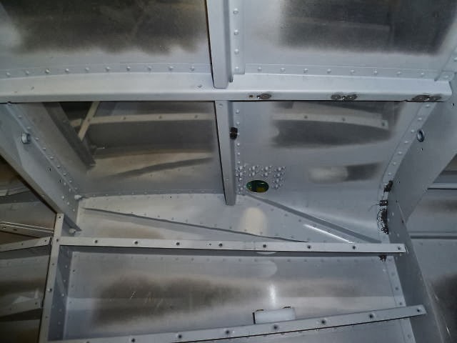
This is the center tunnel cover.  The elevator push tube and electrical wiring will eventually inhabit the center tunnel.  


The upper rear baggage panel is laid out.  Basically it's just cutting big round corners at the top and cutting in  some slots for the seat belts attachment cables to go through.


Beyond this point, there are just some plastic wear blocks to install that protect the rear panels from the seat belt cables, but that's pretty much all there is to the baggage compartment.  The seat pans and forward seat skins shown below are just a bonus for the loyal reader.  You're welcome.


Wednesday, September 25, 2013

Step 9.8, Aft top skins part 2

In the last posting I was unable to finish the aft top skins because I forgot to install the static ports. Here is the left port ProSealed and looking good.


So now I have to get serious about riveting the aft skins on.  The difficulty here is that the skins cover the top of the tail cone and the tail cone is not designed to have people crawling inside of it.  The first thing to do is make some kind of temporary floor in the tail cone to protect the bottom skin -- of the airplane and the person crawling inside.


Some plywood salvaged from the Van's fuselage crate is employed for the temporary floor.  A few cut outs to clear structure and the floor is ready.  The plywood is not resting entirely on the bulkheads though.  I placed blankets and pillows underneath to spread out the load across the bottom skin as well.


After installing the temporary floor I crawled inside to take a look around and found that is was not at all difficult to get in or out and it seemed to take my two hundred pound frame without complaint.

OK, time to get on with it.  The aft top skins having been previously prepared, are clecoed on. Then the rivets are placed and taped down so that they will not jump out when the riveting starts.


My helper has once again elected to buck, so she had to get inside.  She was a pretty good sport about it, only stopping once to request a pillow for her head.  Naturally, her request was denied and she was ordered back to work at once. Kidding, kidding.


I used up the last of my roll of rivet tape.  I've been mostly using masking tape on this project because of the expense for the rivet tape.  The rivet tape works much better.  I had actually forgotten how much better it really is.  I think for my next plane I will just throw caution to the wind and really splurge.  I'll buy two rolls of rivet tape.

Well, here it is.  Aft top skins complete.


Wednesday, September 18, 2013

Step 9.7, Aft top skins and static ports

There are two skins behind cockpit and one in front of it.  Our next step is get the two rear skins on before continuing on to the cockpit interior.  The skins are fairly thick as skins go, and require a significant amount of curvature especially near the tail.  This creates a lot of stress on the clecos when attaching the skins for match drilling because the skins would prefer to stay flat.  The process of attaching the skins will be very familiar to the reader at this point:  Match drill, debur, dimple, and rivet.

Before I could get to all of that I had to install the J-stringers at the top of the bulkheads.  Fortunately, I had already fabricated these when we were doing the stringers for the lower fuselage.  So it was just a matter of sliding them in place.


Match drilling


Debur


Well you get the idea.  Here's Carolina working the cleco pliers...


All of this excitement was too much for our puppy.


Now the skins are dimpled and ready to go back on for the last time.  It was about this time that I heard that now all too familiar sound effect of a record scratching in my head.  I realize that I hadn't installed the static ports.  If I don't to the static ports now I will have to crawl in the the tail cone do it later when it will be much more difficult.  Ordinarily I am predisposed to doing things the hard way, but this time I think I'll take the easier path.

Static ports? What are static ports?  I sense the readers unease as it would now appear likely that I am about to launch off in to another lengthy and oh so tedious discussion of airplane systems and/or history. Relax dear reader, this one will be brief: 

The static port on an airplane is used to measure the local barometric pressure.  This air pressure is then used by various aircraft instruments such as the altimeter and vertical speed indicator. The location of the static port is the most significant aspect of its installation.  It needs to be in an area of relatively undisturbed air in order to get accurate pressure readings.  In the RV's case, the static port is located on the fuselage side in between the wing and horizontal stabilizer.  OK, now I suppose you're thinking, I see what it does and where it's located, but what is it?  Well, that is simple. It's just a tube stuck out in to the wind. Perpendicular to the wind, actually.  So as not to induce ram air pressure.  The RV employs two static ports, one on each side of the fuselage which are connected together.  Having two ports allows the instruments to see the average of the two for a more accurate reading.

The static ports were located on the fuselage's side according to the plans, but I'm using SafeAir brand ports which have a wide base which requires the port to be moved about .25" forward to clear the F-708 bulkhead.


Here is the back of the static port showing the wide flange and the interfering bulkhead.


The inside surface of the skin and the SafeAir static port flange are roughed up and then cleaned while Carol heads to the kitchen to whip up a batch of our favorite.  Yes, it's time to get out the Proseal again.


The static port is bonded to the inside of the fuselage skin.


This is the Tee where the two ports come together.


And this is the static port from the outside.  Not much to look at, really.


 I will end this post here as it has become apparent that our dog Roxy is in need of another exorcism.