Purpose

This is a blog containing the build history of an experimental home built airplane. The RV-7A is a two place, piston powered, low wing, tractor configuration, tricycle gear, aluminum and composite aircraft. The original purpose of this blog was to document the construction of my experimental category aircraft in order to satisfy the build log requirement for the FAA. Now it's just for the amusement of friends and family as I document some of our aviation experiences. For more information on the RV series of aircraft see www.vansaircraft.com.

Sunday, August 9, 2015

Step 13.3, Painting the Fuselage

In early 2010, long before I even began the RV-7A project, I was planing to paint it.  The design of my paint booth depended on the size of my airplane's fuselage.  And the size of my shop depended in part on the size of the paint booth.  It is a really good feeling to finally be at this point now and I am pleasantly surprised to find that the fuselage which is the largest single piece that I will have to paint on this project, just fits.

There were minor dings that were hammered flat and some that needed filling and when that was complete the fuselage was rolled into the booth for primer.


After priming the fuselage was rolled back out for sanding and another round of minor body work.


And then the real fun begins.  Laying out the stripes.  


To lay out the stripes I wanted to first make a paper template so that I could be sure that the stripes would be identical of both sides of the aircraft.  To make the template, I taped some paper down along the length of the fuselage and then went to work adapting my paint scheme drawing to the full sized aircraft.  I went to a lot trouble calculating angles from my drawing, finding tangents at selected points along the curve and then transferring those points to the template in an effort to replicate the drawing exactly at full size.

The big problem with this approach is that it doesn't take into account that the transformation from drawing to fuselage is a transform from 2D to 3D.  Although when viewed exactly straight on from the side the resulting stripes did look like the drawing, there were certain angles that were aesthetically challenged.

In the end, I did a lot of adjustment by eye, as it were, to get the flowing shape I was initially going for.  Once the template was complete the fine-line tape is applied to the fuselage along the edge of the paper, recreating the shape of the stripe.  Flipping the paper over gets the same stripe on the other side of the plane.

Here a stick is employed to hold the rudder cables out away from the fuselage during the painting process.


The first stripe pained is the silver stripe.  The photo below is after the stripe has been painted and the re-taping process is underway.


The stripe is taped off and cover with masking allowing the blue stripe to be completed.  Once both stripes are done the white can be laid down.  Here Carol is preparing the masking for the blue stripe.


Finally, the white goes on and the fuselage is done:


Now, I start the whole process over on the vertical stabilizer and rudder:


There is still a lot of work to do on the paint; the cowling, the wheel pants, and the landing gear fairings, for example.  But the vast majority of the hard work on the painting is done.  The remaining pieces are manageable in size and should not be a major time sink like the fuselage and wings were.

Before I take the fuselage off of the rotisserie, I'll attach the four antennas that go beneath the plane (2 COMM, 1 Transponder, and 1 ADS-B IN).  That leaves 3 antennas to attach on the top side, but I'll save that for later.

Monday, July 13, 2015

Step 13.2, Horizontal Stabilizer, SB

Vans aircraft announced a Service Bulletin a while back that applies to my plane.  The SB requires recurring inspection of a section of the main spar of the horizontal stabilizer that has been shown to develop cracks on some aircraft over time .  This is not a particularly worrisome development -- GA airplanes get these types of service bulletins or ADs (Air worthiness Directives) all the time.

What is a Service Bulletin and how does it differ from an AD?  SB are maintenance recommendations from a manufacturer and do not carry the force of law.  Air worthiness Directives are mandatory compliance issues that come from the FAA.  An AD may reference an SB in which case the SB does become mandatory.  Even though an SB may not be mandatory, it is probably not a good idea to just ignore them.

That Vans Aircraft has responded with the SB and provided a retrofit kit is a good thing and shows that the company is safety conscious and is proactive in maintaining their good reputation. The SB states that the retrofit kit is not required until cracks have developed. As a preventative measure, I have decided to implement the fix anyway since the horizontal stabilizer is not yet on the plane and has not been painted.  There will never be a more convenient time to do the work so I might as well do it now even though it will delay my completion date a few days.

The first step is to disassemble the center section.  This means removing the inside ribs and the attachment flanges.  There are a lot of rivets in here.  The last time I worked on this piece was in early 2012.  I always hoped that I would be get to fly the plane a little before I started tearing it apart.


The rivets attaching the inside ribs are removed.


The horizontal stabilizer main spar is that thin piece of sheet metal in the foreground.  The area of concern are the four rounded notches right at the edge of the skins,  This is, evidently, a high stress area, which is why the notches are placed there in the first place.  The theory behind the notches is that the slow curvature of the inside edge of the notch would allow the stress to flow around this area rather than build up at a single point, resulting in crack formation. 

The theory has worked on most planes, but a few have developed cracks which led to the service bulletin.


The retro fit kit further beefs up this intersection with doubler plates on each side.


The doublers are clecoed in place prior to riveting


This is the front mostly riveted.

And the rear with the doublers visible.


Now the ribs are re-installed.


The final step is to complete the painting.


Horizontal stabilizer service bulletin (and painting) complete!

Wednesday, July 8, 2015

Step 13.1, more painting

Sand, sand, primer, sand, sand, base, base, base, sand, clear, sand, sand, buff. done.  Ok, good, now on to the next piece.  Obviously it's needless to say, but painting is a slow, messy, and often very tedious business.  I comfort myself in the knowledge that I'm saving big bucks here  -- enough to buy fuel for about 5 years worth of flying (assuming the average GA pilot flies about 50 hrs/yr). I plan to fly more than that, but who knows.

After the primer is sanded down to #800, the masking for the stripes begins.  Here the wing tips are masked and ready for the first stripe.  I don't know if this is the most efficient method or not, but I start with the gray stripe.  The when that is on and dry enough, I peel the tape up and re-apply it over the gray, but on the other side of the line so I can mask off the just painted stripe.


Then the blue is applied and re-masked for the white.  Here is Carol preparing the tape for the blue stripe.


Finally after all of the base colors are on there are two coats of clear applied over the top.


On to the next thing.  Carol sanding primer on the left wing.

Here I'm applying 3-M fine line tape to follow paper templates for the stripes.


Here is a wing in the blue stripe phase.


Wing tips and wing after clear coat in the paint booth.  I think the flash must have been off.  I don't think it was really that dark in there.


So at this point, I've done no color sanding or buffing because that can wait. Indefinitely, I think, because there will always be something more fun to do.  I've completed about 1/2 of the painting now with just one really big item, the fuselage to go.  Of course there are numerous smaller items such as the cowling,  the vertical stabilizer, rudder, wheel pants, and fairings to go... 

Tuesday, June 16, 2015

Step 13.0, Time out for a disaster

Gravity sucks.  Yes, it is the weakest of the four fundamental forces, but it still manages to wreak havoc on a macro scale.  While preparing to spray the epoxy primer on the right elevator I somehow caused it to fall off of the hook and slam on to the concrete floor.  Can we say with the telephoto lens of hindsight that its position on the hook was precarious and replete with gravitational potential? Yes, if we must. And since I was holding the other end of the elevator at the time, a far too honest assessment might conclude that I had something to do with the accident. However, we should not fail to toss a wary eye at gravity itself, lest it escape blame entirely.


Did that just happen?  I just stood there in stunned disbelief while my brain worked feverishly to assemble the appropriate profane response.  Fortunately, I had the forethought to stockpile a great reserve of emergency profanity for just such an occasion.  Logistically though, it's not such an easy thing to do. That is, to launch in an instant, the mother of all swear storms that common sense demands.  In a second or two my paralysis fades and I spring into verbal action.  At least that is what I thought would happen.  But I find that I am unable to form intelligible words as I attempt to unload my entire arsenal at the same time.  That ever so small portion of the profane artistry which finally makes it past my vocal cords intact is just one tiny, weeny, almost imperceptible, "shit." All the while, in in my mind, I keep seeing the Hindenburg going up.  Over and over.  Oh, the humanity!  
Now the moment has past and I move on to survey the damage. It seems that the aluminum carnage stops at the first rib tip and there is no sign of bending anywhere except at the inside corner as shown. My first thought is that I will have to build a new elevator or at least re-skin it.  I really did not like the thought of re-skinning because removing rivets often causes as much damage as the original problem.  Since the elevator is small, it might be better to just make a new one.

Then I think, not yet accepting the stark reality of the situation, that perhaps I could just unbend the corner using a screw driver and some pliers.  Well, I had nothing to lose so I gave it a go:


As expected it cracked in several places as the folded metal was pulled out.  It was pretty clear that this was not going to work, so I moved on to plan C.

My next idea was to cut off the corner and replace it with fiberglass.  The photo above shows the cutting process already begun.


Here is the elevator with the corner cut off and the edges smoothed.


The next step is to build a foam core for the corner and epoxy it in place.


Then build up the corner with fiberglass.


And sand it down smoothly feathered into the aluminum.


So I end up with a fiber glass tip and a few hours wasted, but the fix is very strong and virtually invisible.  At least from the top or bottom.  From the end the plug is visible, but I don't think it's obvious what kind of horrors went on there.  It's kind of like some scar you carry from childhood that you laugh about now, but was just short of amusing at the time.


So next time I'll continue with more painting and, hopefully, fewer mishaps.

Friday, June 5, 2015

Step 12.9, Painting begins

And the winner is...


After an extended period of agonizing indecision I've finally made my selection regarding the paint scheme.  My next step is to try and calculate the amount of paint I will need.  The paint store says I will need about 1 gallon per 350 square feet.  Having painted a few cars in the past, I know that I will probably be unable to achieve the very light coats and good coverage that a professional would do. I've had pretty good results with the lay it on heavy and then sand off every thing that doesn't look like a car method.  I'll try that with the airplane.

But how should I estimate paint required?  Hmm... How big is my airplane, I think.  I decide to break the problem down into very small pieces a, la, Leibniz and Newton.  Summing the infinitesimals I arrive at the value 470 square feet.  


There are many possible ways to calculate this, and consequently, many possible sources of error. My confidence in this number is fairly low.  Never-the-less, I trundle off to the paint store and return with this:


There's 1.5 gallons each of primer and base coat, plus two gallons of clear coat.  I have 1/2 gallon of the blue base coat and a quart of the gray.  I figure I will just get started and see how far the paint goes.

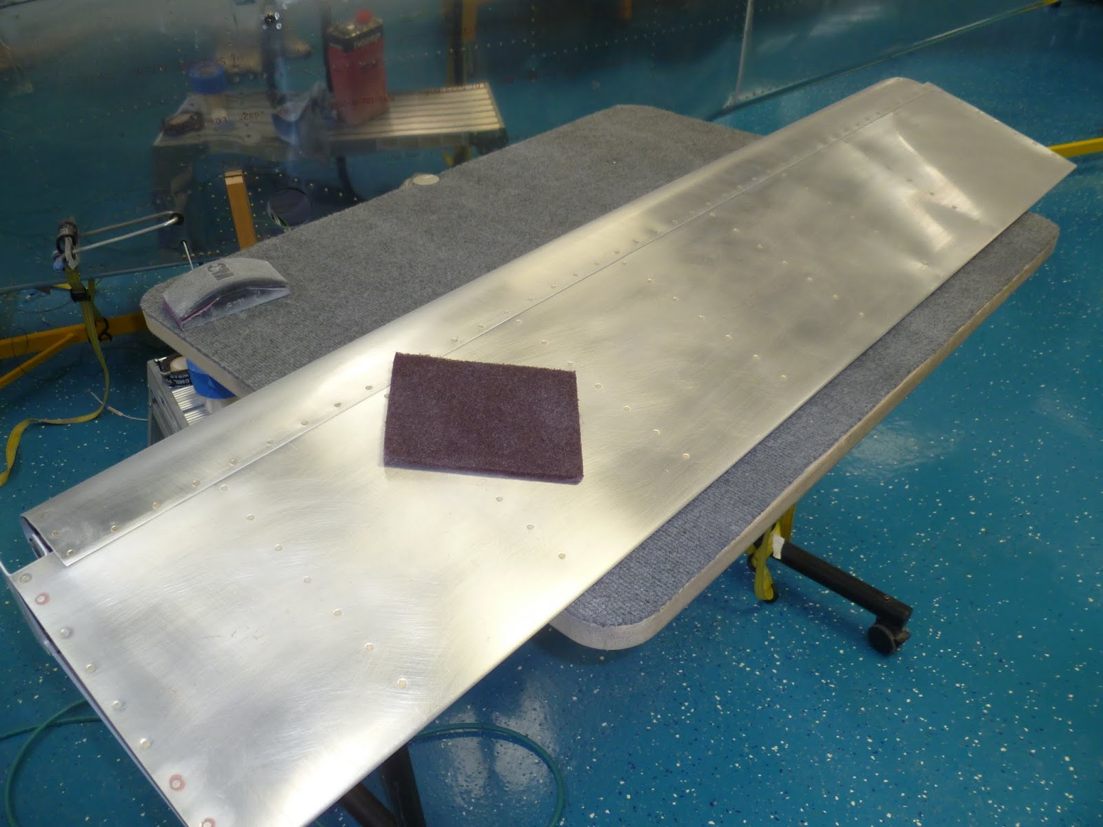
I'll start with the small pieces and work up to the Fuselage.  First scuff with a Scotch pad.  Here is an aileron:


The first coat is epoxy based primer

Here are the flaps and ailerons getting there base and clear coats.  The white is a three part process: Two coats of white base coat, then two mid coats with pearl, and finally two coats of clear over the top.

And the mad painter himself:


Finally, here is the horizontal/vertical stabilizer fairing. All purdy and everything.


The small pieces came out just fine.  I'm now confident that I understand the processes well enough and am ready to move on to the larger and more complicated parts like wings and fuselage.