Purpose

This is a blog containing the build history of an experimental home built airplane. The RV-7A is a two place, piston powered, low wing, tractor configuration, tricycle gear, aluminum and composite aircraft. The original purpose of this blog was to document the construction of my experimental category aircraft in order to satisfy the build log requirement for the FAA. Now it's just for the amusement of friends and family as I document some of our aviation experiences. For more information on the RV series of aircraft see www.vansaircraft.com.

Monday, March 17, 2014

Step 11.4, Forward deck access

Now that the canopy release is finished I can prepare the skin that goes over the top of the front deck.  The front deck, as you may recall, is the area behind the instrument panel up to the firewall.  Most of the avionics will be located in this area.  The only access to this area is from underneath the instrument panel in the foot wells.  It turns out that this is a particularly uncomfortable place to have to work since one must lie on his back arched backward over the main spar.  I've elected to skip this entirely, as fun as it sounds, and install some access panels through the top of the forward skin.  This will come in handy when it is time to rivet the skin on as well as providing future access to the avionics, sans chiropractor.

This is the area that will be covered. Pictured is the forward deck area looking aft:


The first thing is to lay out the holes to be cut in the skin.  When an access port is added through the skin, a backing piece, called a doubler is added that strengthens the area around the hole.  The idea is that stresses in the skin are safely routed around the hole the area of the skin that is doubly thick.  In addition to strengthening the skin, the doubler also provides a flange for the access port cover to rest against.  Pictured below are the doublers and the skin ready to be cut.


Here are the doublers after the saber saw attack.


Then the doublers are match drilled to the skin.


The final step for the skin is to rivet the doublers on and also add some nut plates to secure the covers.  I also sealed the edges of the doubler to discourage water entry at this location.


With the access ports complete all that is left to finish are the covers.  Ordinarily, aluminum would be used here, but in this case I want to mount some GPS antennas underneath.  Instead, I laid up fiber glass which has the fortuitous property of being relatively transparent to radio frequencies. It allows the GPS signals right through.  So I used three layers of 9 oz. cloth to build a thickness that is close to the .032" aluminum skin. Although the fuselage is fairly flat in this area, but I laid up the access panels on top of the skin anyway to get the very slight curve built in.  


Here are the covers trimmed and counter sunk for screws.  At this point they're ready for paint prep.


And that wraps up Access Panels 101.

Wednesday, March 5, 2014

Step 11.3, Receive engine

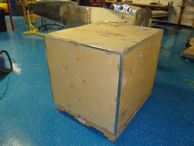
It's here, it's here!  It's finally here!  Yea!


Ok it's just a box. The most expensive box I've ever purchased, but yes, it is just a box.  Until you open it of course.


Now the particulars:  

Brand:      ECI
Model:     TITAN IOX370, horizontally opposed, fuel injected, air-cooled.
Cylinders: 4
Ignition:    Electronic, Dual independent P-Mag
Induction: Normally aspirated
HP:          205

Horsepower-wise the IOX370 is very similar to a modern air cooled automobile engine like that in a Porsche 911 for example.  A normally aspirated, air-cooled 911 made about 315 HP in 6 cylinders.  Take 4 of those and you get about 210 HP at the crank.  The main difference being that the IOX370 is designed to produce its rated power continuously for its 2000 hour lifetime.  This is certainly not recommended for the Porsche owner.


And so it sits waiting on me to finish the fuselage.


Monday, February 24, 2014

Step 11.2, Empennage fairing

This week's task is to finish the empennage fairing.  I've been wanting to take the empennage (vertical and horizontal stabilizers) apart now that they have been fit, so that I could ready them for painting.  One last detail before I can remove them is to fit the empennage fairing.  The fairing is a molded fiberglass part that comes with the finish kit.  It is designed to cover the intersection of the vertical stabilizer, horizontal stabilizer, and fuselage.   As it comes from Van's, the fiberglass is a bit too rough for painting and the fit is, well, less than perfect.  A heat gun is used to make minor adjustments here and there, but some new fiberglass and much sanding is required to fine tune the fit.

In addition to generally improving the fit, I also want to add a lower fairing to it so that the fairing covers the gap above the horizontal stabilizer as well as below it.


So here is the basic fairing as it comes from Van's after trimming the excess.  It's not visible in the picture below, but the fairing does not extend underneath the horizontal stabilizer.  The Van's way to fill this lower gap is to fit a piece of aluminum trim to the fuselage that extends upward to the bottom of the horizontal stabilizer. I've decided to follow the lead of a number of other builders who think it nicer to add a fiber glass fairing to the bottom of the Van's supplied piece.  More on that later...


The elevator torque tubes come from the center of the fuselage area and extend through the fairing.  Carol worked on finding the limits of the tube's movement relative to the fairing. A template was made and the curve transferred to the fairing.  The fiberglass was cut back to the blue line that leaves clearance for the elevator control.


A few other notches and trims later, the fairing was fitting nicely.


The next step is to build the lower fairing.  The aluminum skin is protected with a layer of packing tape.  Then modeling clay is globbed on to pack the lower gap.  I cut a piece of aluminum with the radius that I wanted on the fairing and proceeded to scrape off all of the clay that didn't fit the radius profile.  I slapped on some automobile past wax as a release agent and I was ready to mix epoxy.  Well almost,  I cut out the strips of fiberglass first.


Next came the fiberglass and epoxy.  Four layers of 9oz. BID glass with West Systems epoxy.


It's a couple of days later and much to my surprise, the fairing comes off easily.  There may be a little more epoxy in the layup than is necessary.  The new glass is 10 to 20 thousandths thicker than the Van's supplied piece.  I didn't know ahead of time how many layers Van's used, so I consider myself pretty lucky to get even that close.  Here is the new glass (foreground) grafted on to the Van's piece after the rough trimming.


For filler I used a mixer of epoxy and micro-spheres.  The micro spheres are just little glass bubbles that take up space.  When combined with epoxy they make a very lightweight filler material that is fairly sandable.


These leading edges don't look too good, so I'm forced to go for another round of epoxy.  To get a better fit on the mating surfaces of the vertical and horizontal stabilizer, I'm going to lay up a thin layer of glass on the HS and VS directly over the leading edge part where the fit is poor.  Then, after that is almost set I will re-install the fairing with some wet epoxy on the inside to bond with the thin layer.


Now the fit is pretty good around the entire perimeter.

At this point its just a matter of smoothing everything down, filling pin holes and other minor imperfections in the surface, and match drilling the mounting holes through the fairing to the aircraft structure.

After a coat of primer it's ready for paint.


The empennage fairing has taken much longer than I expected.  Oh, well.  It's the journey not the destination  that's important -- I just have to keep reminding myself.

Saturday, February 1, 2014

Step 11.1, Canopy jettison mechanism

Imagine you're flying along and suddenly everything has just gone to hell.  You have no choice at all, but to leave the aircraft in midair.  In an airplane with a sliding canopy, one just slides it open and out you go.  Alas, it's not so easy in a tip up canopied airplane when the canopy opens against the prevailing wind.  To overcome this obvious design oversight, Van's has thoughtfully provided a canopy release mechanism. Under dire circumstances the canopy may be released from its hinges via the canopy release handle.  The canopy can then be pushed upward and free of the aircraft.

The utility of the canopy release is a ready topic of discussion on-line.  The two main arguments being, one, that it is unlikely that one would be wearing a parachute in the first place, and two, that the release mechanism may not work as designed, especially since its never been tested in flight.  Either way, I think it's still a nice thing to have.  I look at it as a kind of Jesus handle -- pull the handle under emergency circumstances and you'll be meeting Jesus in a jiffy.

But there is another use for the canopy release mechanism, and that is, if you want to remove the canopy for maintenance.  With out the canopy in the way, the interior of the aircraft is much easier to access.  So for this reason I have decided to install the canopy release hardware.

To begin there are a bunch of UHMW (Ultra High Molecular Weight) blocks of polyethylene plastic.  This is the same or very similar to the kind of plastic used for kitchen cutting boards.  It offers excellent durability and very low friction which makes it ideal for use as hinge pin guides and bell crank bearings.


The basic mechanism is a handle protruding through the instrument panel that pulls on a lever attached to a bell crank.  The bell crank turns the action 90 degrees such that when the handle is activated the bell crank pull inward on connecting rods which in turn pull the pins from the canopy hinges.  In the photo below, the lever and connecting rods are visible -- the bell crank assembly is upside down.


And here is the bell crank installed showing the connecting rods withdrawn.


A wider view looking backward towards the back of the instrument panel.  The canopy hinges on the left and right sans canopy. The lever can be seen at center, left of forward deck central rib.  The release handle, not shown, connects to the lever and continues rearward through the instrument panel.


I'll leave the attachment of the handle until after the instrument panel is complete.  So for now, the canopy jettison mechanism is finished.  And so is this post.

Wednesday, January 22, 2014

Step 11.0, Finish kit

At very long last the finish kit has arrived.  The finish kit was ordered from Van's in the last week of September anticipating an 8 week delivery time.  By the time December rolled around I was expecting delivery at any time...  Tick, tock... At the end of December I called Van's to inquire.  It turns out they mailed me a confirmation of my order on October 7 that itself requires a confirmation.  Since I did not receive this confirmation requiring a confirmation, my order was unconfirmed!  Consequently, my order was stalled -- indefinitely, I presume since they already had accepted my deposit and had written authorization to charge the balance to my credit card.

Still, I remained busy on the project during the wait so I can't be too angry about the mix up.  I just feel like I spent a lot of time wondering when, and planning for, the finish kit arrival.  If only I had realized that I had an additional 6 weeks of lead time on this order, I might have been more productive.  Perhaps this might have been a good time to take on Middle East peace or cancer.


And so began the inventory.  The packing list is spread out along the nearest horizontal surface, in this case the right wing.  One at a time the pieces come out of the box, are checked off the list, and then are carried upstairs for temporary storage.


So what's in the finish kit?  Well, not nearly so much as your bank account might expect.  The big items are the canopy, and the fiberglass parts such as the cowling and wheel pants and fairings.  There are also the wheels, brakes, front landing gear leg, swiveling nose wheel fork, and motor mount.


And so it goes.

Saturday, January 11, 2014

Step 10.8, Forward deck

The forward deck is the structure from the instrument panel to the fire wall above the foot well.  There are a lot of little flanges and fiddly bits to fabricate.  They don't take too long so it's best to just power through it.

Which brings me to the frustration of the week:  One might assume that is is possible to complete a sub kit like, oh, let's say hypothetically, the fuselage kit without needing parts from the next kit.  Well, one would be very wrong because in at least two instances that I have run in to recently I have needed parts from the finish kit which I have not yet received.  Specifically, the wing root fairings which are to be fit during the first wing fitting and the F-697 top hat piece which is needed during the front deck assembly.  Both of these parts are called out in the manual during the fuselage assembly but are not provided until the finish kit. Arrgh!  Neither are real show stopppers, but I wasted a lot of time looking for them only to find out that they haven't yet arrived.

The front deck begins with the aforementioned flanges which begin life as aluminum angle of various thicknesses.


They each get cut and drilled in some way,  a few being to get by without having a corner lopped off.  Most of these will be used to mount the instrument panel.


Instrument pannel.


Here are the ribs that make the front deck frame.


I need to make a cut out in the center to accommodate some of the avionics that are a little deeper than Van had originally planned for. 


I will cleco this thing to together prior to a test fit on the fuselage.


Now it's all riveted in place.  The top skin will not be riveted down until everything is complete with in the forward fuselage area.  

So here is a sneak preview on what I'm planning for the panel.  The avionics manufacturers provide full sized stickers of their offerings for panel planning purposes, but I decided not to avail myself of their sticky backed feature.  I'm just using masking tape so I can move them around much easier.


That's it for this week.

Wednesday, January 1, 2014

Year 2 retrospective

Unwavering and implacable, time advances.  January 1, 2014 marks the second anniversary of this project. To me, it seems the pace would challenge a snail's attention and yet, it is remarkable how much has been accomplished in just one year.

On New Year's day 2013, I was still 3 1/2 months shy of completing the wings.  Among other things, I still had the top skins to rivet, and the wing tips fit.


By mid April the fuselage arrived.  I plowed through the fire wall and then began the unending series of ever smaller bulkheads that make up the tail cone structure.


And then came the dreaded bending of the longerons.  It turns out this process is only 95% as bad as its online reputation.  I really could not recommend it for its entertainment value, but as an educational tool, well, let's just say it's an education all by itself.  One is not likely to fully appreciate what an obstinate thing aluminum angle can be -- until you try to beat a curve in to it.


With the longerons shaped, the tail cone was next.


And that was followed by the center section.


Which led to the forward section and the side skins.


Then a rotisserie was constructed.


The tail cone top skin, baggage compartment interior panels and seat pans were next.


At some point the propeller arrived.


And we finished the seat backs. Carol took the first ride.


I'm not sure, but she appears to be steering by reins.  Either way, she's an unconventional pilot flying from the right hand seat.


Eventually, it was time to attach the wings and set their incidence.


And the horizontal and vertical stabilizers were bolted on.


Finally, the roll bar was set.


All of which brings us to the present. Here's to all of the progress of 2013.


Season's Greetings and Best wishes in 2014.