Purpose

This is a blog containing the build history of an experimental home built airplane. The RV-7A is a two place, piston powered, low wing, tractor configuration, tricycle gear, aluminum and composite aircraft. The original purpose of this blog was to document the construction of my experimental category aircraft in order to satisfy the build log requirement for the FAA. Now it's just for the amusement of friends and family as I document some of our aviation experiences. For more information on the RV series of aircraft see www.vansaircraft.com.

Friday, May 1, 2015

Step 12.8, forward top skin

Time to rivet the last skin.  I've put it off as long as possible and now its time to finally rivet or get off of the pot -- as it were.

The main reason to delay is that access under the forward top skin will be limited to underneath from this point on, or at least it would have been, had I not punched access panels into the two center bays.

These access points will provide the ability to do some work in there from above, but the primary method will unfortunately be me, on my back, under the instrument panel, with rudder pedals in my face.  Not too appealing a thought which is why it has taken me so long to get to this point.  I wanted to make as sure as is possible that all of the avionics were working and I was done working under and behind the panel.


With the last skin riveted on, I started on the cowling attachment.  I'm using quarter turn fasteners rather than the hinge and pin method that Van's likes to use.  The quarter turn fasteners are more expensive and probably heavier, but they make it much easier to to get the cowl on and off.

The first order of business for the cowl attachment is to build a flange that holds the quarter turn capture bracket.  This is the part that the quarter turn screw latches on to. The flange goes around the perimeter of the firewall so there is quite a lot of it to make.  I decided to make a template from plywood and then use that to guide a router through the serpentine shape. 


I found out right away that the plywood is not thick enough for the minimum depth of my edging bit on the router, so I had to make another template from 3/4" pine.  It's a shame I didn't just start there, but that would have required some thinking ahead.


And finally we get to the cut raw material and the quarter turn mounting holes finished.


This was a messy process -- a lot of sawdust and metal shavings.


The brackets are riveted on.  Each of the "fingers" on the flange are bent to match the curvature of the cowling.


The strips are then riveted to the fuselage.


And with that, the flanges are complete.

Tuesday, March 3, 2015

Step 12.7, Paint Schemes

I really want to get the fuselage painted before I mount the landing gear or engine because it will be much easier to paint the bottom while the fuselage sits in the rotisserie.  Consequently, I've had to get more serious about designing a paint scheme.  Some of these designs come straight from other planes I've seen (6,7) others are, to the best of my knowledge, new designs reusing common design elements.

I want to have have my favorite colors involved, but at the same time not anything so garish that resale value might be compromised.  I want vibrant, but I don't want to be flying a Nike tennis shoe. Which in hind sight, is kind of ironic because I found that many of the shapes I was drawing looked a lot like the Nike swoosh!

In chronological order of creation but not necessarily preference:

1

2

3

4

5

6

7
I took these seven drawings to our regular Friday night hang out so that I could gather opinions from my some of my friends.  Pictures 4 and 5 garnered the most votes.  With drawing 4 getting one more vote than number 5.  Surprisingly, I think each of the others got at least one vote. In all about ten votes were cast, but without any serious favorite emerging.  It looks like I will have to keep drawing or draw straws.


Wednesday, February 25, 2015

Step 12.6, Rear window

I've been reluctant to install the rear window until now, because of the extreme utility of reaching through the open window to work in the baggage area.  I recently did a test fit of all of the interior components because I knew that some would require trimming and adjustment.  Some of these were in the baggage compartment which is a very small space.  Alas, with that final bit of work behind the seats done, it is now time to glue that window in.

I put the rough cut window on the plane and trimmed up the forward edge so that it met the canopy. Then I had Carol get inside and I taped the window down tightly so that she could mark the inside edges of the fuselage against the window.  Using that as a guide, I set a new line parallel to the one Carol drew giving 1" overlap.


Although she seems to be content to ride back there, but there might be an issue with weight and balance, so I guess Trina will have to ride in the back instead.


The one inch overlap is marked using 1" wide tape.  I checked this three times just to make sure that I was marking the correct side of the drawn line, lest I cut the back window and inch short.  


Well, my natural instinct to do the wrong thing was thwarted this time and the cut came out beautifully.  At this point all I have left to do is sand the edges smooth and apply the glue.  The glue is a marine grade flexible adhesive that is used to attach windows to boats.  There is a primer the goes on the scuffed plastic and aluminum.  The primer is like thinned ABS plastic in look and smell, and it paints on easily.  Once the primer has set for a bit, but less than two hours, the adhesive is applied in a thin coat to both mating surfaces.  The glue is thick and has the consistency of toothpaste.  It is messy, but does not stick well to the polycarbonate window without the primer.  This is a very welcome property as I managed to get excess glue on the window in various places and it rubs right off.


Clamps all around the roll bar and sticks cut to length on the inside hold the window in place.


And there is it is.  One step closer to completion.

Meanwhile, Carol is assembling the last of my PC boards.  This one was a late addition to the project when I discovered that the Ray Allen bargraph displays I used on my panel were incompatible with a Garmin/Vertical Power installation.  It seems that the Vertical Power box biases the position encoders for roll, pitch, and flaps at a level which is beyond that which the bargraph displays are designed to handle.  I had to design yet another board to intercept the signals going to the bargraph displays and re-scale them to fit. 


Naturally, I implemented a complex solution involving a micro controller and RS-232 serial port to do the work of a few resistive dividers -- `cause that's how I roll...

Tuesday, January 13, 2015

Year 3 retrospective

My third year of this project is now complete.  Reviewing the progress this year, it seems the that pace has slowed considerably.  I'm now officially in the 90% complete with only 90% to go phase.   This is not such a good place to be as it is impossible to answer the inevitable questions regarding the completion date.  Well, I wish I knew, but the best I can guess right now is about 6 months.  I usually underestimate everything by 3X so perhaps I won't be done until late 2016.

To begin year 3, the finish kit arrived in the last week of January 2014.  I was already working on the vertical to horizontal stabilizer fairing so I continued on that whilst Carol did the inventory.


This year we discontinued the dress code.

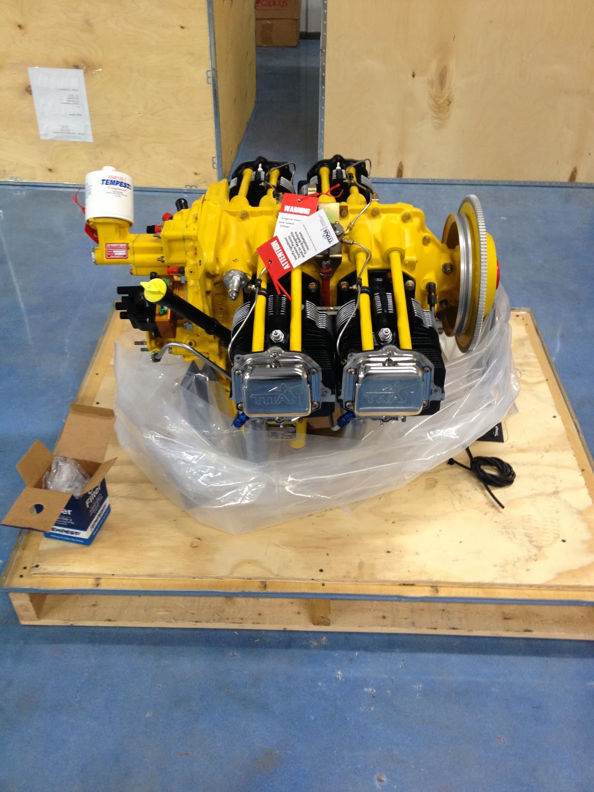
And best of all, this year my engine arrived.


Next up was the canopy.  This is a major time sink that continued right on through October.


I'm not sleeping.  Just trying to crawl out of the cockpit, under the cross bar and into the baggage compartment, while the canopy glue was setting.  Fortunately, this is not the usual method of egress.


A lot of the work this year occurred in my home office on the panel design and my custom PC boards.


And the wiring went on and on...


We made cables.


And Carol assembled our PC boards while Trina slept.  Roxy kept the shop free of squirrels.


And so at year's end I have the wiring (mostly) complete behind the firewall and some of the avionics calibration is done.


Here is the panel powered up for the first time.


So I have done a few things this year.  I'm looking forward to finishing the electronics which seems a lot like work to me.  Next up, I begin to think seriously about painting.


Thursday, November 20, 2014

Step 12.5, Wiring continued

Wiring an airplane is a test of dogged determination. Or should I say uncommon perseverance. I guess they're really the same thing.  But this is just a thing that begs saying it twice. Perhaps it's a bit of an exaggeration.  I think not.  It seems that this phase of the project is destined to continue for centuries.

Does this explain why airplanes didn't exist before the 20th century?  Might they have been begun in the middle ages and only finished recently?  No one knows.

One thing I am certain of is that I'm wearing the gloss off of my formerly shiny shop floor wandering about looking for the wire stripper or the crimper.  Not that one, the one that fits these special connector pins.  When I finally get the right tools in place, I forget which pin I'm connecting, spawning yet another trip across the shop to recheck the already thoroughly rechecked plans.

When I get past this phase I'll be crowned the Ultimate Wiring Champion and perhaps have my own reality show.  Or not, either way I'll be finished with this and moving on.


It is not particularly difficult as there really are no inaccessible places or stubborn fasteners to encourage frustration.  It's just a lot of checking, rechecking, making labels, and crimping connectors.

Then there is the oft' repeated episode where I forget to slip on the heat-shrink tubing before the connector goes on.  Some may remember a very similar difficulty I faced when I would forget to slip on the B-nut before flaring the ends of the fuel and brake lines.  Arrrg!


Here's a look at the most common crimp connector pins that I'm using. It surprised me that I was able to assemble all of them in one place for this photo.  These boogers have a knack for staying out of sight when you need them.


A wing makes a handy work surface / schematic holder


And so it goes.  One wire at a time.  When I finish this page, I'll just have 6 more to go.


Monday, November 3, 2014

Step 12.4, Home built avionics

Just when it looks like I might be making some actual progress on this project, I find a new way to slow it down.  One might reasonably assume that I've missed my calling;  That with a skill such as this, I could have been a mid-level manager.  Perhaps.  But I digress...

The most recent impediment to my project's completion is the idea that I should make some of my own avionics.  I'm not talking about anything big, like a radio or auto pilot.  Something really small, I tell myself, should be no trouble at all.  Like an annunciator panel or relay deck.  How hard could it really be?  They're so small.

With this truly terrible idea rattling about in the back of my consciousness, I then compounded the injury to my project by inventing several new solutions that have yet to be matched with actual problems. In all, I've identified 5 circuit boards to make.

The screen on the right shows the circuit layout underway for a few of them.  Clockwise from the top:  annunciator panel, relay deck, and two copies of the control column serializer.  The screen on the left is my instrument panel which was also being designed at the same time.


Now without further adieu.  The five boards my project can not live with out are:

Annunciator Panel:  This is a set of lights that signal changes in various conditions within the aircraft.  There are six conditions monitored by my annunciator: Master warning,  Master caution, Low oil pressure, Low voltage, Canopy not locked, Auxiliary fuel pump on.  The six lights are also push-buttons that are monitored by a microprocessor whose principal responsibility is watching the input signals and updating the status of the lights -- on, off, or flash.  The big advantage of having a microprocessor do all of this is that it is more complicated.

There are some people who think that 8 indicators are the absolute minimum for an annunciator panel, but I've settled for only six because somehow six seems less ostentatious.

WIG/WAG Controller:  A potential problem at an uncontrolled airport is an aircraft or other vehicle pulling out onto the runway when you are about to land.  One way to reduce the likelihood of this occurring is to increase your visibility from the ground.  The wig/wag controller does this by alternately flashing the taxi and landing lights.  A microprocessor interprets the state of three switches from the instrument panel, Landing light, Taxi light and Wig/Wag enable and then sets its outputs appropriately to control the landing and taxi lights.  

Relay Deck: A relay deck is just a collection of relays.  My implementation of a relay deck contains 10 relays and, --- wait for it --- a microprocessor.  Relays such as these are typically used to isolate low current instrument panel switches from higher powered devices like motors. In my case, I need the relays for the trim motors, flap motor, and the push to talk switch.  In addition, I wanted to reduce the size of the wire bundle going down through the control columns by serializing the data emanating from the stick mounted switches.  The serial data input function (on a relay deck) is not available commercially as far as I am aware.  My relay deck has three data channels for input.  One serial channel each for the pilot and passenger, and one parallel channel that permits panel mounted switches to get in on the act as well.  All of this allows me more flexibility on how and when the relays should be activated and by whom.

Control Column Serializer:  This board reads the control column switches that are mounted within the grips and converts this data to a serial data stream going to the relay deck.  The data are packetized and a CRC is computed to validate the data's integrity at the receiving end.

Fuel Capacity Transducer: This board is required to translate the fuel tank's quantitative transducer, which is of the capacitive type, to an analog voltage that the Garmin EFIS (Electronic Flight Information System) can then use to then display the fuel quantity on the PFD (Primary Flight Display).

Pictured below are the 5 bare boards listed above, plus a sixth (bonus) board at right that doesn't do anything -- well, it doesn't seem to do a lot because it simply translates some signals from the Honeywell AML34 instrument panel switches. (how useful could it really be without a microprocessor?)


I've always felt that any problem worth fixing can be made more complex by adding a computer to it's solution.  It's a kind of occupational hazard for me.  I just can't help myself.

At the core of each of these boards are 8 bit micro controllers of various types.  Having a computer right there surely invites feature creep which is the enemy of CPS (Completed Plane Syndrome), so I'll have to watch that.  I've already added the ability for a couple of these boards to listen to the Garmin EFIS RS-232 serial data stream.  Whether or not I'll do anything with that data source remains to be seen. At the very least, it will be something I can play with after I finish the plane.

At this point I've built the 5 boards and have tested 4 of them.  A lot more software will have to be written before they are finished, but at this point I'm just trying to verify the correctness of the hardware before I move on.  I'll have more to say about them in upcoming posts.  By then I will have had a chance to learn some new acronyms.  TTFN.


Tuesday, October 21, 2014

Step 12.3, Designing the panel

It turns out that making the instrument panel is not such a hard thing to do, but there are a few questions that must be answered first.  Probably the most important question from a monetary point of view is whether or not the panel will be IFR certified (Instrument Flight Rules).  The cost of an IFR panel is largely dictated by the FAA requirement that the GPS and or VOR  and or localizer receivers be certified to operate within the national air traffic system.  This alone can easily add $10K to the cost of the full featured Visual Flight Rules panel.

With that in mind, it looks like I'll be doing a VFR panel, but what exactly does this mean?  A panel equipped for VFR flight means the aircraft is instrumented for flight under Visual Flight Rules. Basically, the aircraft can be operated only under clear weather conditions. This does not seem to be such a large impediment to me, since I don't have a burning desire to fly in inclement weather nor am I certified to do so.

Next question, how will the panel be in instrumented, that is, what style of instruments to choose?

The most basic choice is between a Glass panel or a panel with steam gauges.  Despite the confusing name, a glass panel is not actually made of glass.  It simply refers generically to an instrument panel that displays its data on some kind of screen, usually an LCD like a computer monitor.  Likewise, steam gauges do not actually measure steam pressure.  The term 'steam gauge' refers, in a somewhat derogatory fashion, to the round dials that traditionally adorn the aircraft instrument panel.

One of the big advantages of a glass panel is that all or most of the instruments are displayed on a single screen.  This can simplify the panel and reduce weight.  It also permits new functionality to be added to the display without having to physically change the panel.  On the other hand, one big advantage to the steam gauge approach is that if the power should go off, the steam gauges won't know it -- they don't need power to operate.

Alas, I chose the glass panel approach because it is the more modern way, and it offers the most flexibility going forward.  Still, I'm not entirely comfortable with the little problem of power or the accidental loss of of it, so I will be adding a separate ASI (AirSpeed Indicator) and altimeter, both steam gauges.  

Deciding the location and number of switches and their function was the hard part for me.  Since I had already decided the number of displays I wanted (2) and the brand that I would be using, Garmin, a lot the functionality has already been decided for me.  What remains mostly reduces to turning on or off lights or avionics.  To get started, I made a list of the things I thought I might like to control:

  • Master power / Alternator field enable
  • Engine start / mag select -- key switch
  • Auxiliary fuel pump
  • Avionics master
  • Autopilot Enable
  • Control Column passenger enable
  • Strobe light
  • Navigation lights
  • Taxi light
  • Landing light
  • flaps
  • pitch trim
  • roll trim
  • Wig Wag enable
  • Pitot heat
  • Seat heat
  • Dome light
To arrange the switches I followed the idea that the switches should be placed in roughly the order they might be used in a typical flight, left to right.  This order makes about as much sense as any other, with the added advantage that this order will utterly befuddle any Hebrew, or Chinese plane robbers :)

With all that settled, I then laid out the panel using online software from frontpanelexpress.com. Their software allows one to import the panel outline, which I downloaded from Van's in dxf format. This way I could be sure that the panel would fit properly.  I was also able to get some pre-made 'macros' (FrontPanel express terminology) for some of the switches and instruments online.  One RV7 builder in particular, Brian Chesteen, was very helpful.  After that it's just a matter of placing the components, or rather, the cut-outs for them.  There is a lot of measuring involved to get the sizes of the switches and other components properly specified.  A fair amount of guessing is required.  Like how much clearance is needed over here or how much to allow for powder coat over there.  And so it goes...


When the design is finished, the front panel express application totals up the machine time it will take to cut the panel and how many tool changes are required.  It then gives you the bad news, which of course is the price. 

This is the point where I returned to the design to try and reduce the number of tool changes, as well as reducing the sizes and the number of labels as well.  After a few iterations, I got the price down some and simplified the panel a bit.  Both of which are good things.  It is a simple matter to place the order right from the application.  All they really need is your credit card and shipping address. Everything else is specified in the application while you design the panel. The cost of the panel includes infilled engraved labels which are done by the CNC router along with all of the other machining.  Sending this work out probably saved me a month of work.

And the finished panel?  Glad you asked:


My next task is to begin attaching the instruments to the panel.  A bit of filing was necessary here and there. but there were no show-stoppers.  I made adjustments to the design file, so if I ever need to order another it should be perfect.

Bracketry to hold the radio stack.

AML34 switches by Honeywell.  Custom engraved caps by engravers.net

Once all of the switches are in, there is still a lot of wiring to do on the back side.


And here is the nearly completed panel being test fit.


Very briefly, the two LCD screens on the left half of the panel will display the flight data and moving map, respectively.  In the center are the backup ASI and altimeter. To the right is the radio stack containing (top to bottom) the auto pilot panel, the audio panel, and two GTR-200 COM radios.  The big hole to the right of the radio stack is the glove compartment.  Finally, across the bottom are the aforementioned switches.

A cover plate below the second radio allows room for future expansion.  The radio stack was sized to allow a GTN-650 NAV/COM/GPS radio to replace one of the GTR-200 radios + cover plate.  This will convert the panel to a fully certified IFR panel.  The panel is ready -- I'm just waiting to win the lottery now.  And if the lottery doesn't pan out I still have a long lost relative from Nigeria that died and left me a pile of cash.  I just need to pay some expediting fees and...

The one item on the panel that was not previously mentioned is the annunciator panel. It's the row of 6 colored switches located just above the second LCD display.   That will be the subject of an upcoming post.