Purpose

This is a blog containing the build history of an experimental home built airplane. The RV-7A is a two place, piston powered, low wing, tractor configuration, tricycle gear, aluminum and composite aircraft. The original purpose of this blog was to document the construction of my experimental category aircraft in order to satisfy the build log requirement for the FAA. Now it's just for the amusement of friends and family as I document some of our aviation experiences. For more information on the RV series of aircraft see www.vansaircraft.com.

Tuesday, June 16, 2015

Step 13.0, Time out for a disaster

Gravity sucks.  Yes, it is the weakest of the four fundamental forces, but it still manages to wreak havoc on a macro scale.  While preparing to spray the epoxy primer on the right elevator I somehow caused it to fall off of the hook and slam on to the concrete floor.  Can we say with the telephoto lens of hindsight that its position on the hook was precarious and replete with gravitational potential? Yes, if we must. And since I was holding the other end of the elevator at the time, a far too honest assessment might conclude that I had something to do with the accident. However, we should not fail to toss a wary eye at gravity itself, lest it escape blame entirely.


Did that just happen?  I just stood there in stunned disbelief while my brain worked feverishly to assemble the appropriate profane response.  Fortunately, I had the forethought to stockpile a great reserve of emergency profanity for just such an occasion.  Logistically though, it's not such an easy thing to do. That is, to launch in an instant, the mother of all swear storms that common sense demands.  In a second or two my paralysis fades and I spring into verbal action.  At least that is what I thought would happen.  But I find that I am unable to form intelligible words as I attempt to unload my entire arsenal at the same time.  That ever so small portion of the profane artistry which finally makes it past my vocal cords intact is just one tiny, weeny, almost imperceptible, "shit." All the while, in in my mind, I keep seeing the Hindenburg going up.  Over and over.  Oh, the humanity!  

Now the moment has past and I move on to survey the damage. It seems that the aluminum carnage stops at the first rib tip and there is no sign of bending anywhere except at the inside corner as shown. My first thought is that I will have to build a new elevator or at least re-skin it.  I really did not like the thought of re-skinning because removing rivets often causes as much damage as the original problem.  Since the elevator is small, it might be better to just make a new one.

Then I think, not yet accepting the stark reality of the situation, that perhaps I could just unbend the corner using a screw driver and some pliers.  Well, I had nothing to lose so I gave it a go:


As expected it cracked in several places as the folded metal was pulled out.  It was pretty clear that this was not going to work, so I moved on to plan C.

My next idea was to cut off the corner and replace it with fiberglass.  The photo above shows the cutting process already begun.


Here is the elevator with the corner cut off and the edges smoothed.


The next step is to build a foam core for the corner and epoxy it in place.


Then build up the corner with fiberglass.


And sand it down smoothly feathered into the aluminum.


So I end up with a fiber glass tip and a few hours wasted, but the fix is very strong and virtually invisible.  At least from the top or bottom.  From the end the plug is visible, but I don't think it's obvious what kind of horrors went on there.  It's kind of like some scar you carry from childhood that you laugh about now, but was just short of amusing at the time.


So next time I'll continue with more painting and, hopefully, fewer mishaps.

Friday, June 5, 2015

Step 12.9, Painting begins

And the winner is...


After an extended period of agonizing indecision I've finally made my selection regarding the paint scheme.  My next step is to try and calculate the amount of paint I will need.  The paint store says I will need about 1 gallon per 350 square feet.  Having painted a few cars in the past, I know that I will probably be unable to achieve the very light coats and good coverage that a professional would do. I've had pretty good results with the lay it on heavy and then sand off every thing that doesn't look like a car method.  I'll try that with the airplane.

But how should I estimate paint required?  Hmm... How big is my airplane, I think.  I decide to break the problem down into very small pieces a, la, Leibniz and Newton.  Summing the infinitesimals I arrive at the value 470 square feet.  


There are many possible ways to calculate this, and consequently, many possible sources of error. My confidence in this number is fairly low.  Never-the-less, I trundle off to the paint store and return with this:


There's 1.5 gallons each of primer and base coat, plus two gallons of clear coat.  I have 1/2 gallon of the blue base coat and a quart of the gray.  I figure I will just get started and see how far the paint goes.

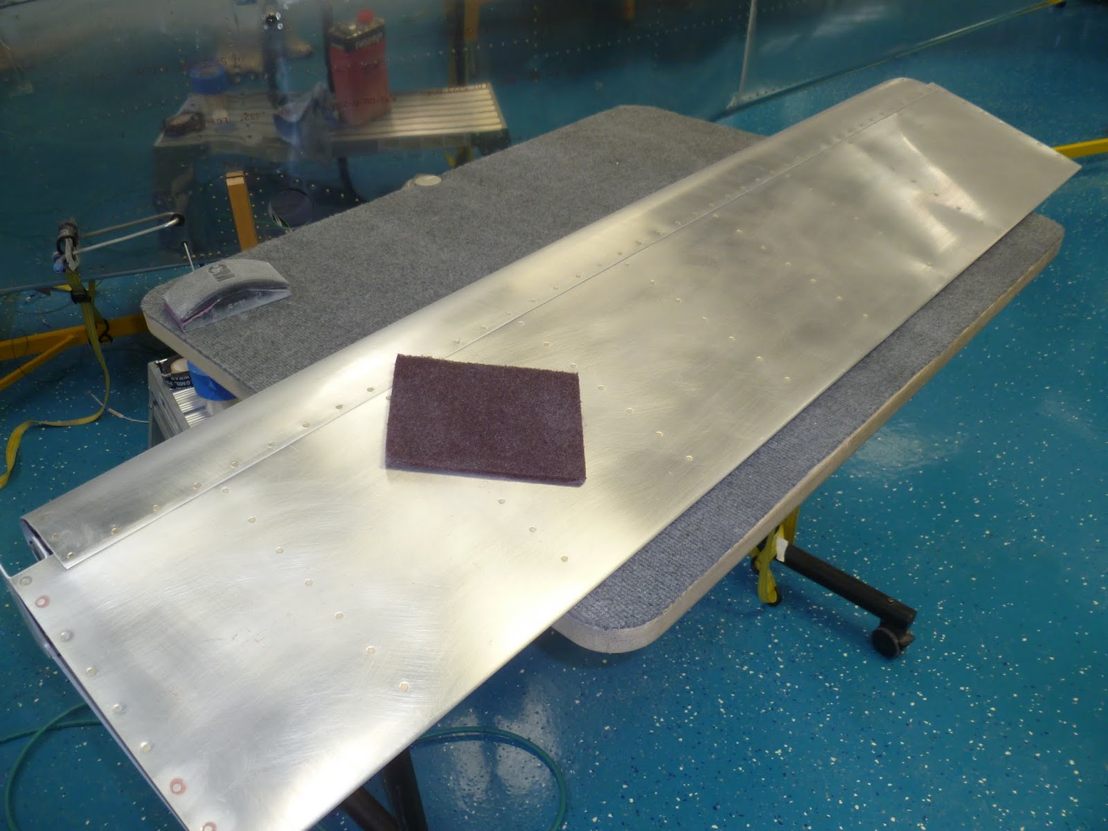
I'll start with the small pieces and work up to the Fuselage.  First scuff with a Scotch pad.  Here is an aileron:


The first coat is epoxy based primer

Here are the flaps and ailerons getting there base and clear coats.  The white is a three part process: Two coats of white base coat, then two mid coats with pearl, and finally two coats of clear over the top.

And the mad painter himself:


Finally, here is the horizontal/vertical stabilizer fairing. All purdy and everything.


The small pieces came out just fine.  I'm now confident that I understand the processes well enough and am ready to move on to the larger and more complicated parts like wings and fuselage.


Friday, May 1, 2015

Step 12.8, forward top skin

Time to rivet the last skin.  I've put it off as long as possible and now its time to finally rivet or get off of the pot -- as it were.

The main reason to delay is that access under the forward top skin will be limited to underneath from this point on, or at least it would have been, had I not punched access panels into the two center bays.

These access points will provide the ability to do some work in there from above, but the primary method will unfortunately be me, on my back, under the instrument panel, with rudder pedals in my face.  Not too appealing a thought which is why it has taken me so long to get to this point.  I wanted to make as sure as is possible that all of the avionics were working and I was done working under and behind the panel.


With the last skin riveted on, I started on the cowling attachment.  I'm using quarter turn fasteners rather than the hinge and pin method that Van's likes to use.  The quarter turn fasteners are more expensive and probably heavier, but they make it much easier to to get the cowl on and off.

The first order of business for the cowl attachment is to build a flange that holds the quarter turn capture bracket.  This is the part that the quarter turn screw latches on to. The flange goes around the perimeter of the firewall so there is quite a lot of it to make.  I decided to make a template from plywood and then use that to guide a router through the serpentine shape. 


I found out right away that the plywood is not thick enough for the minimum depth of my edging bit on the router, so I had to make another template from 3/4" pine.  It's a shame I didn't just start there, but that would have required some thinking ahead.


And finally we get to the cut raw material and the quarter turn mounting holes finished.


This was a messy process -- a lot of sawdust and metal shavings.


The brackets are riveted on.  Each of the "fingers" on the flange are bent to match the curvature of the cowling.


The strips are then riveted to the fuselage.


And with that, the flanges are complete.

Tuesday, March 3, 2015

Step 12.7, Paint Schemes

I really want to get the fuselage painted before I mount the landing gear or engine because it will be much easier to paint the bottom while the fuselage sits in the rotisserie.  Consequently, I've had to get more serious about designing a paint scheme.  Some of these designs come straight from other planes I've seen (6,7) others are, to the best of my knowledge, new designs reusing common design elements.

I want to have have my favorite colors involved, but at the same time not anything so garish that resale value might be compromised.  I want vibrant, but I don't want to be flying a Nike tennis shoe. Which in hind sight, is kind of ironic because I found that many of the shapes I was drawing looked a lot like the Nike swoosh!

In chronological order of creation but not necessarily preference:

1

2

3

4

5

6

7
I took these seven drawings to our regular Friday night hang out so that I could gather opinions from my some of my friends.  Pictures 4 and 5 garnered the most votes.  With drawing 4 getting one more vote than number 5.  Surprisingly, I think each of the others got at least one vote. In all about ten votes were cast, but without any serious favorite emerging.  It looks like I will have to keep drawing or draw straws.


Wednesday, February 25, 2015

Step 12.6, Rear window

I've been reluctant to install the rear window until now, because of the extreme utility of reaching through the open window to work in the baggage area.  I recently did a test fit of all of the interior components because I knew that some would require trimming and adjustment.  Some of these were in the baggage compartment which is a very small space.  Alas, with that final bit of work behind the seats done, it is now time to glue that window in.

I put the rough cut window on the plane and trimmed up the forward edge so that it met the canopy. Then I had Carol get inside and I taped the window down tightly so that she could mark the inside edges of the fuselage against the window.  Using that as a guide, I set a new line parallel to the one Carol drew giving 1" overlap.


Although she seems to be content to ride back there, but there might be an issue with weight and balance, so I guess Trina will have to ride in the back instead.


The one inch overlap is marked using 1" wide tape.  I checked this three times just to make sure that I was marking the correct side of the drawn line, lest I cut the back window and inch short.  


Well, my natural instinct to do the wrong thing was thwarted this time and the cut came out beautifully.  At this point all I have left to do is sand the edges smooth and apply the glue.  The glue is a marine grade flexible adhesive that is used to attach windows to boats.  There is a primer the goes on the scuffed plastic and aluminum.  The primer is like thinned ABS plastic in look and smell, and it paints on easily.  Once the primer has set for a bit, but less than two hours, the adhesive is applied in a thin coat to both mating surfaces.  The glue is thick and has the consistency of toothpaste.  It is messy, but does not stick well to the polycarbonate window without the primer.  This is a very welcome property as I managed to get excess glue on the window in various places and it rubs right off.


Clamps all around the roll bar and sticks cut to length on the inside hold the window in place.


And there is it is.  One step closer to completion.

Meanwhile, Carol is assembling the last of my PC boards.  This one was a late addition to the project when I discovered that the Ray Allen bargraph displays I used on my panel were incompatible with a Garmin/Vertical Power installation.  It seems that the Vertical Power box biases the position encoders for roll, pitch, and flaps at a level which is beyond that which the bargraph displays are designed to handle.  I had to design yet another board to intercept the signals going to the bargraph displays and re-scale them to fit. 


Naturally, I implemented a complex solution involving a micro controller and RS-232 serial port to do the work of a few resistive dividers -- `cause that's how I roll...

Tuesday, January 13, 2015

Year 3 retrospective

My third year of this project is now complete.  Reviewing the progress this year, it seems the that pace has slowed considerably.  I'm now officially in the 90% complete with only 90% to go phase.   This is not such a good place to be as it is impossible to answer the inevitable questions regarding the completion date.  Well, I wish I knew, but the best I can guess right now is about 6 months.  I usually underestimate everything by 3X so perhaps I won't be done until late 2016.

To begin year 3, the finish kit arrived in the last week of January 2014.  I was already working on the vertical to horizontal stabilizer fairing so I continued on that whilst Carol did the inventory.


This year we discontinued the dress code.

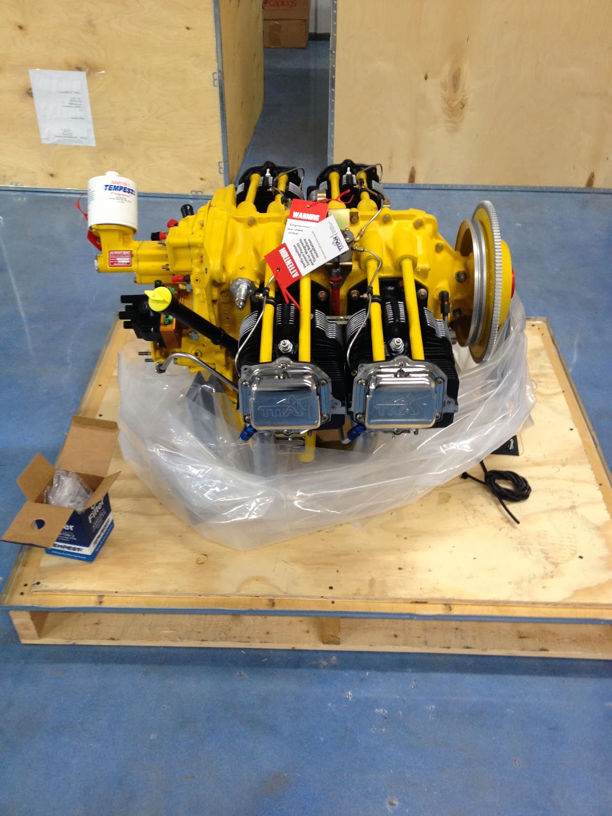
And best of all, this year my engine arrived.


Next up was the canopy.  This is a major time sink that continued right on through October.


I'm not sleeping.  Just trying to crawl out of the cockpit, under the cross bar and into the baggage compartment, while the canopy glue was setting.  Fortunately, this is not the usual method of egress.


A lot of the work this year occurred in my home office on the panel design and my custom PC boards.


And the wiring went on and on...


We made cables.


And Carol assembled our PC boards while Trina slept.  Roxy kept the shop free of squirrels.


And so at year's end I have the wiring (mostly) complete behind the firewall and some of the avionics calibration is done.


Here is the panel powered up for the first time.


So I have done a few things this year.  I'm looking forward to finishing the electronics which seems a lot like work to me.  Next up, I begin to think seriously about painting.